

Industrial Electrical Testing Solution


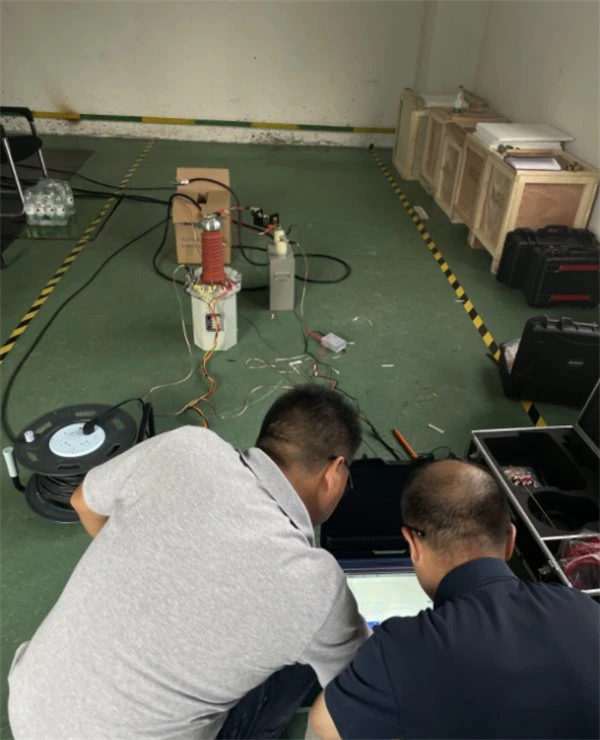
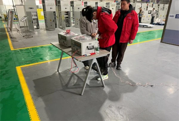
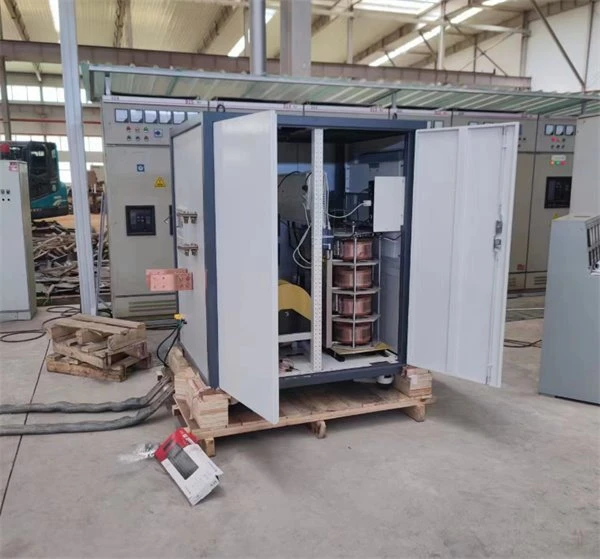

Industrial electrical systems are built around continuous production. In a manufacturing plant, mine, petrochemical facility, steel mill, cement plant, data center, or large processing facility, electrical equipment is not an isolated installation. Transformers, switchgear, motors, cables, generators, protection systems, batteries, grounding networks, and control systems work together as one power distribution system.
A failure in one section can affect an entire production line.
For a plant owner or EPC contractor, electrical testing is therefore closely related to commissioning quality, equipment condition, production continuity, and personnel safety. The testing program must cover both individual equipment and the electrical connections between them.
From the UHV perspective, an industrial electrical testing solution is built around the actual plant power architecture:
Utility Grid → Main Substation → Transformer → Switchgear → Distribution → Cable → Motor / Generator / Production Equipment
UHV provides testing equipment for:
- Industrial Substations
- Manufacturing Plants
- Petrochemical Facilities
- Steel Mills
- Cement Plants
- Mining Projects
- Power Plants
- Oil & Gas Facilities
- Water Treatment Plants
- Data Centers
- Large Commercial & Industrial Buildings
- EPC Electrical Projects
The testing scope can cover transformer testing, switchgear testing, cable testing, circuit breaker testing, CT/PT testing, relay protection testing, insulation testing, partial discharge testing, grounding testing, battery testing, and AC withstand testing.
1. Testing Background
Industrial electrical systems normally operate under demanding conditions.
Large motors start and stop frequently. Variable-frequency drives generate electrical harmonics. Transformers remain energized for long periods. Medium-voltage cables may run through cable trenches, underground ducts, process areas, and outdoor sections. Dust, humidity, chemicals, vibration, and temperature changes can further affect electrical equipment.
These conditions make electrical testing necessary at several stages.
Factory Testing
Electrical equipment is tested before delivery.
Typical equipment includes:
- Transformers
- Switchgear
- Circuit Breakers
- CT/PT
- Cables
- Protection Relays
- Generators
- Motors
Factory testing establishes baseline performance data.
Site Acceptance Testing
After transportation and installation, site testing verifies whether the equipment remains within the specified condition.
Typical checks include:
- Insulation
- Wiring
- Grounding
- Cable connections
- Mechanical operation
- Transformer condition
- Switchgear operation
- Protection circuits
A transformer that passed factory inspection can still develop a problem during transportation or installation. Site testing is therefore an independent verification stage.
Commissioning
The final stage is not simply a collection of individual equipment tests.
The commissioning team needs to verify the complete electrical chain:
Incoming Power → Transformer → Switchgear → Protection → Distribution → Load
For example, a protection relay may operate correctly during an individual test, but the complete trip circuit still needs to be checked through the actual circuit breaker.
2. Testing Objects


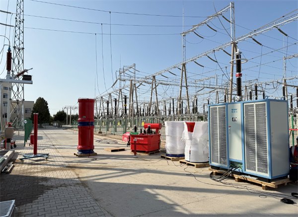


2.1 Power Transformers
Transformers are usually the main voltage conversion equipment in an industrial power distribution system.
Typical tests include:
- Transformer Turns Ratio
- Winding Resistance
- Insulation Resistance
- Tan Delta
- Excitation Current
- Transformer Oil BDV
- Partial Discharge
- AC Withstand where required
For operating plants, test results can also be compared against previous maintenance records.
2.2 Switchgear
Industrial switchgear can operate at medium or high voltage depending on the plant.
Testing may include:
- Insulation Resistance
- AC Withstand
- Contact Resistance
- Circuit Breaker Timing
- Interlocking
- Mechanical Operation
- Protection Functions
2.3 Circuit Breakers
Circuit breakers must interrupt fault current reliably.
UHV circuit breaker testing can evaluate:
- Opening Time
- Closing Time
- Travel
- Speed
- Coil Current
- Contact Resistance
- Phase Synchronization
- Operating Sequence
2.4 Medium- and High-Voltage Cables
Industrial plants often have extensive cable networks.
Testing can include:
- Insulation Resistance
- VLF Testing
- AC Hipot
- AC Resonance
- Sheath Testing
- Partial Discharge
- Cable Fault Location
For long cable circuits, cable capacitance is an important parameter when selecting an AC test system.
2.5 Motors
Industrial motors are among the most frequently operated electrical loads.
Testing may include:
- Insulation Resistance
- Polarization Index
- Withstand Voltage
- Stator Testing
- Rotor Testing
- Inter-Turn Testing
- Impulse Testing
- Tan Delta where applicable
Large motors may require more detailed insulation diagnostics before commissioning or after major maintenance.
2.6 Generators
Where industrial facilities have captive generation or backup generation systems, testing may include:
- Stator Insulation
- Rotor Insulation
- Inter-Turn Testing
- AC Withstand
- Partial Discharge
- Tan Delta
- Winding Resistance
2.7 CT/PT
CT and PT systems are essential for:
- Protection
- Measurement
- Metering
- Energy Management
Testing includes:
- Ratio
- Polarity
- Excitation
- Burden
- Accuracy
- Winding Resistance
- Insulation
- Knee Point for applicable CTs
2.8 Relay Protection
Industrial protection systems may include:
- Overcurrent
- Earth Fault
- Differential
- Overvoltage
- Undervoltage
- Overfrequency
- Underfrequency
- Directional
- Motor Protection
- Transformer Protection
The relay should be tested together with the relevant CT/PT inputs and trip circuit.
2.9 Battery & DC Systems
Industrial substations often use batteries for:
- Circuit breaker operation
- Protection
- Control
- Emergency systems
- Communication equipment
Testing can include:
- Cell Voltage
- Internal Resistance
- Capacity
- Discharge
- Charger
- DC Insulation
2.10 Grounding System
Grounding is critical in industrial facilities because large metal structures, process equipment, cable trays, transformers, motors, and switchgear can all require bonding.
Testing may include:
- Ground Resistance
- Ground Grid
- Continuity
- Step Voltage
- Touch Voltage
- Equipment Bonding
3. Testing Requirements
Industrial electrical testing requirements vary significantly between plants.
The test plan should consider:
- Plant voltage level
- Installed capacity
- Transformer rating
- Switchgear configuration
- Cable length
- Motor capacity
- Generator capacity
- Protection architecture
- Grounding design
- Environmental conditions
- Applicable standards
- Owner's specifications
- EPC commissioning requirements
New Industrial Facility
A typical project sequence is:
Factory Test → Installation Inspection → Site Acceptance → Pre-Commissioning → Energization → Load Commissioning
Existing Industrial Facility
Maintenance testing focuses more on condition changes.
For example:
- Increasing transformer Tan Delta
- Increasing cable PD
- Increasing breaker contact resistance
- Longer breaker operating time
- Reduced battery capacity
- Abnormal motor insulation resistance
Historical data can be useful for deciding whether a component requires further inspection.
4. Testing Methods
4.1 AC Withstand Testing
AC withstand testing verifies the dielectric strength of electrical insulation.
Typical industrial applications include:
- Switchgear
- Transformers
- Cables
- Motors
- Generators
- GIS
For high-capacitance test objects, UHV can configure an AC Resonant Test System according to the required test voltage and capacitance.
4.2 Partial Discharge Testing
Partial discharge testing detects localized electrical activity within insulation.
Potential defects include:
- Internal voids
- Surface discharge
- Floating particles
- Poor insulation interfaces
- Cable termination defects
- Transformer insulation defects
Industrial plants can have substantial electrical interference caused by:
- Variable-frequency drives
- Motors
- Welding equipment
- Inverters
- Switching devices
The PD system therefore needs appropriate sensors and noise suppression for field conditions.
4.3 Transformer Testing
A comprehensive transformer testing program can include:
Turns Ratio
Checks the actual transformation ratio and phase relationship.
Winding Resistance
Checks winding connections and winding condition.
Insulation Resistance
Evaluates insulation between windings and ground.
Tan Delta
Provides information about dielectric losses in insulation.
Excitation Current
Helps identify abnormalities in the magnetic circuit and winding system.
Transformer Oil BDV
Evaluates the dielectric strength of transformer oil.
Partial Discharge
Detects localized insulation defects.
4.4 Cable Testing
Industrial cable testing depends on voltage level, cable construction, length, and insulation type.
VLF Testing
Used for specified medium-voltage cable field testing.
AC Hipot
Used where an AC withstand test is required.
AC Resonance
Suitable for high-voltage cable systems with substantial capacitance.
Sheath Testing
Checks the cable sheath insulation.
PD Testing
Identifies localized cable insulation or accessory defects.
Cable Fault Location
Determines the location of a failed cable section.
4.5 Circuit Breaker Testing
Circuit breaker testing covers:
Electrical Contact + Mechanical Operation
Measurements include:
- Opening Time
- Closing Time
- Travel
- Speed
- Coil Current
- Contact Resistance
- Phase Synchronization
Abnormal timing may indicate mechanical wear, coil problems, control circuit issues, or operating mechanism problems.
4.6 CT/PT Testing
CT/PT testing verifies the measurement and protection signal chain.
Typical sequence:
Ratio → Polarity → Excitation → Burden → Accuracy → Insulation
For protection CTs:
Knee Point → Saturation → Excitation Curve
may also be required.
4.7 Relay Protection Testing
Relay protection is generally tested through secondary injection.
The test system provides controlled:
Current
Voltage
Frequency
Phase Angle
Harmonics
The test sequence verifies:
Pickup → Operating Time → Logic → Trip Output
The final commissioning test should continue through:
Relay → Trip Circuit → Circuit Breaker
4.8 Motor Testing
For large industrial motors, electrical testing may include:
Insulation Resistance
Polarization Index
DC Resistance
Withstand Voltage
Tan Delta
Partial Discharge
Inter-Turn Testing
Impulse Testing
Impulse testing is particularly relevant when evaluating turn-to-turn insulation.
4.9 Generator Testing
Industrial generators can be tested for:
Stator Insulation
Rotor Insulation
Winding Resistance
Inter-Turn Insulation
AC Withstand
Tan Delta
Partial Discharge
4.10 Grounding Testing
Grounding testing may include:
Earth Resistance
Ground Grid Resistance
Continuity
Step Voltage
Touch Voltage
Bonding
For large industrial plants, the grounding network should be considered as a complete system.
5. Recommended Equipment
|
Testing Area |
UHV Equipment |
Application |
|
Transformer |
Transformer Comprehensive Tester |
Transformer diagnostics |
|
Transformer |
TTR Tester |
Turns ratio |
|
Transformer |
Winding Resistance Tester |
Winding testing |
|
Transformer |
Tan Delta Tester |
Insulation diagnostics |
|
Transformer |
Oil BDV Tester |
Oil testing |
|
Cable |
VLF Hipot Tester |
MV cable testing |
|
Cable |
AC Hipot Tester |
AC withstand |
|
Cable |
AC Resonant Test System |
HV cable testing |
|
Cable |
Cable PD System |
Cable diagnostics |
|
Cable |
Cable Fault Locator |
Fault location |
|
Switchgear |
AC Resonant Test System |
AC withstand |
|
Breaker |
Circuit Breaker Analyzer |
Timing / travel |
|
Breaker |
Contact Resistance Tester |
Contact resistance |
|
CT/PT |
CT/PT Analyzer |
Ratio / polarity / excitation |
|
Protection |
Relay Protection Test Set |
Relay testing |
|
Motor |
Motor Surge / Impulse Tester |
Inter-turn testing |
|
Motor |
Insulation Tester |
Insulation testing |
|
Generator |
PD / Tan Delta System |
Generator insulation |
|
Battery |
Battery Discharge Tester |
Battery capacity |
|
Grounding |
Ground Resistance Tester |
Grounding system |
6. Testing Procedure
Step 1 - Review Electrical Documentation
The UHV testing team should first review:
- Single-line diagram
- Equipment list
- Transformer data
- Switchgear data
- Cable schedule
- Motor list
- Generator data
- CT/PT specifications
- Protection drawings
- Battery specifications
- Grounding drawings
- Factory test reports
Step 2 - Visual Inspection
Inspect:
- Equipment installation
- Cable connections
- Grounding
- Terminal connections
- Switchgear assembly
- Transformer condition
- Circuit breaker mechanism
- Motor terminals
Step 3 - Primary Equipment Testing
Transformer
Ratio
→ Winding Resistance
→ Insulation
→ Tan Delta
→ Excitation Current
→ Oil BDV
→ PD where required
Switchgear
Insulation
→ Contact Resistance
→ AC Withstand
Circuit Breaker
Timing
→ Travel
→ Contact Resistance
Step 4 - Cable Testing
Insulation
→ Sheath
→ VLF / AC Withstand
→ PD where required
→ Fault Location if necessary
Step 5 - Motor & Generator Testing
Check:
- Winding Resistance
- Insulation Resistance
- Polarization Index
- Withstand
- Inter-Turn
- Impulse
- Tan Delta / PD where required
Step 6 - CT/PT Testing
Verify:
- Ratio
- Polarity
- Excitation
- Burden
- Accuracy
- Insulation
Step 7 - Protection Testing
Verify:
- Relay settings
- Pickup
- Operating time
- Logic
- Interlocking
- Trip circuit
- Circuit breaker operation
- Alarm signals
Step 8 - Battery Testing
Check:
- Cell voltage
- Internal resistance
- Capacity
- Discharge
- Charger
- DC insulation
Step 9 - Grounding Testing
Verify:
- Ground grid
- Equipment grounding
- Bonding
- Ground resistance
- Continuity
- Step/touch voltage where required
Step 10 - Integrated Commissioning
The final sequence should verify:
Incoming Power
→ Transformer
→ Switchgear
→ Protection
→ Distribution
→ Motor / Generator / Production Load
The purpose is to verify that individual test results translate into correct operation of the complete industrial electrical system.
7. Applicable Standards
Industrial electrical testing may involve IEC, IEEE, EN, national standards, utility requirements, equipment manufacturer specifications, and EPC project standards.
Common reference standards include:
- IEC 60076 - Power Transformers
- IEC 62271 Series - High-Voltage Switchgear
- IEC 60255 Series - Measuring Relays and Protection Equipment
- IEC 60840 - High-Voltage Cables
- IEC 62067 - Extra-High-Voltage Cables
- IEC 60034 Series - Rotating Electrical Machines
- IEC 61936 - Power Installations Exceeding 1 kV AC
- IEC 60099 Series - Surge Arresters
Depending on the facility, additional standards may include:
- IEEE standards
- NFPA requirements
- Local electrical codes
- Utility requirements
- Owner specifications
- EPC commissioning standards
The final acceptance values should be based on the specific project documentation and applicable edition of the standard.
8. Test Parameters
|
Equipment |
Main Parameters |
|
Transformer |
Rated voltage, capacity, ratio, resistance, Tan Delta |
|
Switchgear |
Rated voltage, current, insulation, test voltage |
|
Circuit Breaker |
Rated current, opening time, closing time, travel |
|
Cable |
Voltage, length, capacitance, test voltage |
|
Motor |
Rated voltage, current, insulation, winding resistance |
|
Generator |
Rated voltage, capacity, winding resistance, insulation |
|
CT |
Ratio, burden, knee point, excitation |
|
PT |
Ratio, burden, accuracy |
|
Relay |
Current, voltage, frequency, phase angle |
|
Battery |
Voltage, capacity, discharge current |
|
Grounding |
Resistance, continuity, step/touch voltage |
Cable Test System Selection
The key data are:
Cable Voltage + Cable Length + Cable Capacitance + Required Test Voltage + Test Frequency
AC Resonant Test System
The required system capacity depends strongly on:
Test Voltage × Test Object Capacitance × Test Frequency
The actual configuration should be calculated from the project test requirements rather than selected only by nominal voltage.
Motor Testing
Important information includes:
- Rated voltage
- Rated power
- Motor type
- Winding configuration
- Insulation class
- Test voltage
- Number of phases
9. Common Testing Problems
Transformer
Abnormal Winding Resistance
Possible causes:
- Loose connection
- Tap changer contact problem
- Winding deformation
- Poor terminal connection
High Tan Delta
Potential causes:
- Moisture
- Aging
- Contamination
- Insulation deterioration
Cable
VLF Failure
Potential causes:
- Cable insulation damage
- Termination defects
- Moisture
- Installation damage
- Incorrect test connection
Sheath Failure
Possible causes:
- Mechanical damage
- Water ingress
- Poor installation
- External impact
Switchgear
High Contact Resistance
Potential causes:
- Contact oxidation
- Contact wear
- Poor pressure
- Loose connection
AC Withstand Failure
Possible causes:
- Insulation contamination
- Moisture
- Foreign particles
- Internal insulation defects
Circuit Breaker
Excessive Opening Time
Potential causes:
- Mechanism wear
- Coil problems
- Control circuit fault
- Mechanical adjustment
Unequal Phase Timing
Possible causes:
- Mechanism adjustment
- Mechanical wear
- Pole mechanism problem
Motor
Low Insulation Resistance
Possible causes:
- Moisture
- Dirt
- Aging
- Winding deterioration
Abnormal Inter-Turn Test
Possible causes:
- Turn insulation damage
- Manufacturing defects
- Winding movement
- Thermal aging
Protection
Typical problems include:
- Incorrect CT ratio
- CT polarity error
- PT wiring error
- Wrong relay setting
- Incorrect phase sequence
- Trip circuit failure
Testing should therefore cover the complete signal and trip chain.
Grounding
Grounding problems can originate from:
- Broken connections
- Corrosion
- Poor bonding
- Ground conductor damage
- Incorrect installation
A ground resistance value alone may not provide a complete assessment of a large industrial grounding network.
10. Equipment Selection Guide
Manufacturing Plant
Recommended equipment:
- Transformer Tester
- Switchgear Tester
- Circuit Breaker Analyzer
- CT/PT Analyzer
- Relay Protection Tester
- Cable Tester
- Ground Resistance Tester
Steel Mill
Steel mills contain large motors, transformers, drives, and high-current electrical systems.
The testing package may require:
- Transformer Testing
- Motor Testing
- Cable Testing
- Circuit Breaker Testing
- Protection Testing
- Grounding Testing
Particular attention should be paid to large motor insulation and switchgear contact resistance.
Petrochemical Plant
A petrochemical facility may require testing for:
- Transformers
- MV Switchgear
- Motors
- Cables
- Protection
- Grounding
- Emergency power systems
The project may also have strict requirements for equipment installation and electrical safety.
Mining Project
Mining electrical systems can involve:
- Long cable runs
- Large motors
- Mobile equipment
- Transformers
- MV switchgear
- Grounding systems
Cable testing and grounding evaluation can become major parts of the commissioning program.
Data Center
A data center typically requires strong attention to:
- Transformers
- UPS
- Switchgear
- Generator
- Battery
- Protection
- Grounding
Testing should verify both normal power supply and backup power paths.
Equipment Selection Data
Before UHV prepares a project-specific testing package, provide:
- Plant Type
- Voltage Level
- Installed Capacity
- Transformer Capacity
- Cable Voltage & Length
- Cable Capacitance
- Motor Ratings
- Generator Ratings
- Switchgear Type
- Circuit Breaker Type
- CT/PT Specifications
- Protection Functions
- Battery Voltage & Capacity
- Grounding Design
- Required Test Items
- Applicable Standards
11. Case Studies
Case Study 1 - Manufacturing Plant Commissioning
A new manufacturing facility requires complete electrical commissioning before production begins.
The UHV testing scope includes:
Transformer
→ Ratio
→ Winding Resistance
→ Insulation
→ Tan Delta
→ Oil BDV
MV Switchgear
→ Insulation
→ AC Withstand
→ Contact Resistance
Circuit Breaker
→ Timing
→ Travel
→ Coil Current
Cables
→ Insulation
→ Sheath
→ VLF
Protection
→ CT/PT
→ Relay
→ Trip Circuit
Grounding
→ Ground Resistance
→ Continuity
The complete commissioning sequence then verifies the connection from the incoming supply to the production distribution system.
Case Study 2 - Industrial Motor Maintenance
A large industrial motor has been operating continuously for several years.
The maintenance team performs:
- Insulation Resistance
- Polarization Index
- Winding Resistance
- Inter-Turn Testing
- Impulse Testing
- Tan Delta / PD where applicable
The results are compared with previous records and manufacturer specifications.
This approach helps determine whether the motor can return to service or requires additional maintenance.
Case Study 3 - Petrochemical Plant Cable Testing
An industrial plant has extensive medium-voltage cable circuits.
Before energization, the test team performs:
Insulation
→ Sheath
→ VLF
→ PD where required
For a failed cable, fault location equipment can then be used to identify the approximate fault position before repair work begins.
Case Study 4 - Industrial Substation Maintenance
An operating plant performs periodic testing of its main substation.
The maintenance program includes:
- Transformer Tan Delta
- Winding Resistance
- Circuit Breaker Timing
- Contact Resistance
- CT/PT Testing
- Relay Testing
- Battery Capacity
- Ground Resistance
Comparing current results with historical data helps identify changes in equipment condition.
12. FAQ
Q: What Is Included In Industrial Electrical Testing?
A: It can include transformers, switchgear, circuit breakers, cables, motors, generators, CT/PT, protection relays, batteries, and grounding systems.
Q: Why Is Electrical Testing Important Before Industrial Plant Commissioning?
A: Testing identifies installation and equipment problems before energization and verifies that protection, switching, grounding, and distribution systems operate according to the project requirements.
Q: Can UHV Provide A Complete Industrial Testing Package?
A: Yes. UHV can configure transformer, cable, switchgear, protection, motor, generator, battery, and grounding testing equipment according to the plant electrical system.
Q: What Information Is Needed To Select A Cable Testing System?
A: The main information is:
Cable voltage
Cable type
Cable length
Cable capacitance
Required test voltage
Required test frequency
Q: When Should AC Resonance Be Used?
A: AC Resonance is suitable for high-voltage test objects with relatively high capacitance, particularly long cable systems and certain large electrical equipment.
Q: Can UHV Provide Transformer Testing Equipment?
A: Yes. UHV transformer testing equipment can cover turns ratio, winding resistance, insulation resistance, Tan Delta, excitation current, oil BDV, and partial discharge where required.
Q: What Is Tested On Industrial Motors?
A: Depending on motor type and project requirements:
Insulation Resistance
Polarization Index
Winding Resistance
Withstand Voltage
Inter-Turn
Impulse
Tan Delta
Partial Discharge
Q: Does Industrial Electrical Testing Include Protection?
A: Yes. Protection relay testing verifies pickup, operating time, logic, trip output, and coordination with the actual circuit breaker.
Q: Is Grounding Testing Necessary For Industrial Plants?
A: Yes. Grounding provides an important path for fault current and supports electrical safety. Large facilities should evaluate grounding, bonding, and continuity according to the project design.
Q: Can The Same Equipment Be Used For Commissioning And Maintenance?
A: In many cases, yes. The test equipment can be configured for both new installation commissioning and periodic maintenance, although the required test methods and acceptance criteria may differ.
Q: Can UHV Customize Equipment For An EPC Project?
A: Yes. UHV can configure equipment according to the project's voltage levels, test objects, required test items, standards, and field conditions.
13. Related Products
Transformer Testing
- Transformer Turns Ratio Tester
- Winding Resistance Tester
- Insulation Resistance Tester
- Tan Delta Tester
- Transformer Oil BDV Tester
- Transformer Comprehensive Tester
Cable Testing
- VLF Hipot Tester
- AC Hipot Tester
- AC Resonant Test System
- Cable Sheath Tester
- Cable Partial Discharge Tester
- Cable Fault Locator
Switchgear & GIS Testing
- AC Resonant Test System
- Partial Discharge Test System
- SF6 Gas Analyzer
- SF6 Dew Point Meter
- Contact Resistance Tester
Circuit Breaker Testing
- Circuit Breaker Analyzer
- Contact Resistance Tester
- Dynamic Resistance Tester
CT/PT Testing
- CT/PT Analyzer
- CT Analyzer
- PT Analyzer
- CT Excitation Tester
Motor & Generator Testing
- Motor Surge / Impulse Tester
- Insulation Resistance Tester
- Tan Delta Tester
- Partial Discharge Test System
- Winding Resistance Tester
Protection Testing
- Relay Protection Test Set
- Three-Phase Relay Tester
- Secondary Injection Test System
Battery Testing
- Battery Discharge Tester
- Battery Capacity Tester
- Battery Internal Resistance Tester
Grounding Testing
- Ground Resistance Tester
- Ground Grid Tester
- Earth Resistance Tester
- Grounding Continuity Tester
14. Request a Quote
Industrial Electrical Testing Solution from UHV
Industrial electrical testing should be planned around the plant's actual electrical architecture rather than a single piece of equipment.
UHV can build a testing package around:
- Incoming Power
- Transformer
- Switchgear
- Circuit Breaker
- CT / PT
- Protection
- Cable
- Motor / Generator
- Battery
- Grounding
- Industrial Loads
The equipment configuration can be determined according to the required test voltage, test current, test frequency, measurement range, cable capacitance, equipment rating, and project standards.
Send Your Project Information
Industrial Facility Type
→ Manufacturing / Steel / Cement / Mining / Petrochemical / Data Center / Other
- Plant Voltage
- Installed Capacity
- Transformer Capacity
- Switchgear Type
- Circuit Breaker Type
- Cable Voltage & Length
- Cable Capacitance
- Motor Ratings
- Generator Ratings
- CT/PT Specifications
- Protection Functions
- Battery Voltage & Capacity
- Grounding System
- Required Test Items
- Applicable Standards
- Factory / Site / Commissioning / Maintenance
UHV Testing Scope
- Transformer Testing
- Switchgear Testing
- Circuit Breaker Testing
- Cable Testing
- Motor Testing
- Generator Testing
- CT/PT Testing
- Relay Protection Testing
- Insulation Testing
- Partial Discharge Testing
- AC Withstand Testing
- Battery Testing
- Grounding Testing
- Cable Fault Location
For a complete industrial electrical testing quotation, UHV recommends providing the single-line diagram, equipment list, transformer parameters, cable schedule, motor and generator ratings, protection configuration, grounding design, and required testing standards.
This information allows UHV to determine the appropriate test voltage, output capacity, test frequency, measurement range, and equipment combination before the project equipment is selected.
Send your industrial electrical testing requirements to UHV and request a project-specific testing solution and quotation.