
Transformer Tester
A transformer tester is a device used to evaluate the performance and condition of electrical transformers.
Testing Insulation Resistance
Transformers have insulation to prevent electrical leakage. A transformer tester can measure the insulation resistance to ensure it meets safety standards and to detect any deterioration in the insulation over time.
Turns Ratio Testing
This test determines the turns ratio of the transformer, which is crucial for voltage transformation. Any deviation from the specified turns ratio can indicate winding errors or faults.
Winding Resistance Measurement
Transformer windings should have low resistance to minimize losses and ensure efficiency. The tester measures the resistance of the primary and secondary windings to check for any abnormalities or damage.
Impedance Testing
Impedance testing assesses the impedance of the transformer under load conditions. It helps in determining the voltage regulation and efficiency of the transformer.
Polarity Testing
Ensures the correct polarity of windings, which is essential for proper operation and voltage transformation.
Load Testing
Load testing evaluates the performance of the transformer under various load conditions. It helps in assessing the efficiency, voltage regulation, and overall functionality of the transformer.
Short-Circuit Testing
Detects any short circuits in the windings or other components of the transformer.
Frequency Response Analysis
This test assesses the frequency response characteristics of the transformer, which is crucial for applications where frequency stability is essential.
Partial Discharge Measurement
Partial discharge testing detects partial discharge activities within the transformer insulation, which could lead to insulation breakdown if left unattended.


features of transformer tester
Transformer testers are specialized devices used to evaluate the performance, condition, and safety of electrical transformers.
Petrochemical Solutions
Transformer testers can accurately measure the turns ratio of transformers, ensuring that they meet design specifications. This feature helps identify any winding errors or faults that may affect performance.
01
Winding Resistance Measurement
They measure the resistance of transformer windings to detect any abnormalities or damage. This measurement helps assess the efficiency and condition of the transformer.
02
Insulation Resistance Testing
Transformer testers assess the insulation integrity of transformers by measuring insulation resistance. This test ensures that the transformer insulation is capable of withstanding the operating voltage and prevents electrical leakage.
03
Polarity Testing
These testers verify the polarity of transformer windings to ensure correct connections and prevent damage due to incorrect polarity.
04
Short-Circuit Impedance Testing
Transformer testers measure the impedance of the transformer under short-circuit conditions. This test helps assess the transformer's ability to withstand short-circuit currents and ensures safety and reliability.
05
Load Testing
They evaluate the performance of transformers under various load conditions to assess voltage regulation, efficiency, and overall functionality.
06
Partial Discharge Measurement
Some advanced transformer testers can detect partial discharge activities within the transformer insulation. This test helps identify potential insulation weaknesses that could lead to failure.
07
Frequency Response Analysis
Transformer testers analyze the frequency response characteristics of transformers to ensure stability and performance in applications where frequency variations are critical.
08
Data Logging and Analysis
Many transformer testers feature data logging capabilities to record and store test results for analysis and documentation purposes. This enables technicians to track trends, identify issues, and make informed maintenance decisions.
09
Safety Features
Like high voltage testers, transformer testers incorporate various safety features such as overload protection, insulation shielding, and safety interlocks to protect operators and equipment from electrical hazards.
10
Digital Display and Interface
Transformer testers often feature digital displays for easy reading of test results and may have user-friendly interfaces for intuitive operation.
11
Portable and Benchtop Models
Transformer testers come in both portable and benchtop models to suit different testing environments and applications. Portable models are convenient for field use, while benchtop models offer higher precision and functionality for laboratory or industrial testing.
12
These features collectively enable transformer testers to perform comprehensive testing and analysis, ensuring the reliability, safety, and efficiency of electrical transformers in various industries and applications.
types of products
Transformer Tester have following type for meeting the different test requirements

UHV-310 Sweep Frequency Response Analyzer
Or Transformer winding deformation tester is mainly composed of laptop and the main host, it is mainly for test the transformer winding deformation and make sure the winding inside of the transformer is in good condition.
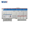
UHV-315 Automatic Transformer Test Bench
Is a kind of comprehensive transformer test system And it is used for conduct the transformer characteristic test including:
(1)Transformer no-load performance test
(2)Transformer load performance test
(3)Transformer power-frequency voltage test
(4)Transformer frequency doubling withstand voltage test
(5)Transformer winding DC resistance test
(6)Transformer transformation ratio / phase test
(7)Transformer Insulation resistance test
(8) Partial Discharge test
(9)Temperature Rise test
(10)Transformer zero sequence test
(11)Transformer noise test
(12)Lightning impulse test etc.
The system mainly composed of main Transformer Test Bench, Intermediate Frequency Generator Set, Intermediate Step-up Transformer, Induction Electric Voltage Regulator High Voltage Auxiliary Control Cabinet and AC Test Transformer etc.


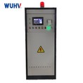
UHV series Transformer DC Winding Resistance Tester
Is mainly for test the winding resistance of the transformer or high voltage reactor, it can effectively detecting possible faults such as welding, loose connection parts, missing strands, and broken wires in transformer winding or coil. The equipment divided into different model (UHV-5A,UHV-10A,UHV-20A,UHV-40A,UHV-50A) according to its different current output (5A, 10A, 20A, 40A, 50A,100A), and there are also extra model three circuit model like UHV-S10A and UHV-S20A.
UHV-321 Transformer Capacity Load No-load Tester
Mainly for test the transformer’s capacity, no-load characteristics and short-circuit losses, Zero sequence impedance,and have harmonic analysis function, It can also automatically perform waveform distortion correction, temperature correction, voltage correction (no-load test under non rated voltage), current correction (short-circuit test under non rated current conditions)


UHV-331 Transformer Turns Ratio Tester
Mainly for measure the Transformer’s turns ratio and group for different transformer, the equipment’s transformation ratio testing range: 0.8~10000, group testing range: 1~12 and its testing accuracy is 0.5%~0.2%.
It have fast test speed and wide testing range which can reach 10000:1.and can automatically save 99 groups test data. Also have transformer short-circuit protection and interturn short-circuit protection functions. In case of short circuit, relevant information will be displayed on the LCD screen in characters.
UHV-342 Transformer Capacitance & Tan-Delta Tester
Is mainly for measure the transformer’s capacitance and tan delta value, which can estimated whether the insulation condition is good or not., its output voltage range: 0~12kV, it have UST, GST,CVT and GSTg four different test method. The equipment is It adopts high-power switching power supply, which outputs 45Hz and 55Hz pure sine wave and automatically increase the voltage to a maximum value 12 KV. It can filter 50Hz interference automatically, and it is applicable to the site test of substation and other places with large electromagnetic interference.

UHV-4000 Transformer On-Load Tap-Changer Tester
Is mainly for measure the transition waveform, transition time, transient resistance values at each moment, and three-phase synchronization of the transformer's on-load tap changer.It can automatically calculate the transition resistance values and transition time values and have U disk storage function for storing more data and waveform.
Maintenance or precaution of the Transformer Tester
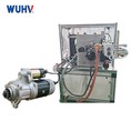
The Transformer test bench is mainly composed by main Transformer Test Bench, Intermediate Frequency Generator Set, Intermediate Step-up Transformer, Induction Electric Voltage Regulator, High Voltage Auxiliary Control Cabinet and AC Test Transformer etc.
- Before use, remove the generator leads, clean the casing and body dirt, and keep the surface of the body dry and clean;
- Connect the test circuit according to the above diagram (note that the test wire should be disconnected at this time);
- Once the preparation work and safety measures are ready, press the "Start" button. (If the equipment cannot be started at this time, it is possible that the regulator has not returned to the zero position. Slowly adjust the regulator knob back and hear a slight click before starting again.) Slowly adjust the regulator knob until the voltage reaches 800V. After a no-load test of the equipment, return the regulator to zero;
- If the equipment is working properly, connect the output line to the test object;
- Power on without display: Turn off the device first, open the fuse box of the AC 220V socket on the backplane, check if the fuse is burnt out, and replace the fuse.
- Screen suddenly goes black: You can press the reset button to restart the measurement.
- Incorrect measurement and calculation results: Check the external wiring, whether it is operated according to the manual, and whether there are any poor contacts or incorrect wires; The relevant parameter settings are incorrect.
- The measured voltage is normal but the current shows zero. Please check if the fuse of this current level is blown.
- When using the dual meter method for wiring, there is a wiring error prompt. Please carefully check the on-site wiring according to the manual. If the wiring is confirmed to be correct, please replace the voltage regulator A/C two-phase and try again to determine if
- the three-phase power supply phase sequence on site is incorrect.
- The results of the no-load test have significant fluctuations. Please note that the test power supply needs to be separated from the power supply used for high-power impact equipment such as workshop cranes.
Why choose us
Your reliable supplier for Transformer Tester
Wuhan UHV Power Technology CO., LTD. is a well-known High Voltage Tester supplier, And we specialize in the production variety of different transformer Tester including:
- UHV-310 Sweep Frequency Response Analyzer
- UHV-315 Automatic Transformer Test Bench
- UHV series Transformer DC Winding Resistance Tester
- UHV-321 Transformer Capacity Load No-load Tester
- UHV-331 Transformer Turns Ratio Tester
- UHV-342 Transformer Capacitance & Tan-Delta Tester
- UHV-4000 Transformer On-Load Tap-Changer Tester
Professional Technical Team And Rich Experience
We have been in transformer tester manufacturing more than 20 years. And we offer engineers help you installing the equipment and provide free technical advice services. And can our engineer can also flight to your workshop or test site to help guide the installation, connection, commission and operation.
Strong Technique Ability
We have tens of experienced engineers, can achieve your customize requirements, such us add the new function, change the software or menu, change the appearance or shape etc. We develop 2~3 new production line for new product and also update the several existing product every year to make sure our product is competitive and powerful.
Rapid response and quick shipment
We can response the customer in several minutes, then provide customer the quotation and manual within 1 hour and provide solution within 24 hours. And the lead time of our product is relatively short for 3-5 working days, some stock goods can be shipped immediately within 1 day.
our service
- UHV provides professional installation, commissioning and training for users’ workers, ensures that users can get familiar with operation methods and put machines into use as soon as possible;
- UHV provides one year warranty and lifetime maintenance. Free repair for mechanical failure and parts damage (no human factors and force majeure factors) under warranty (replacement parts except wearing parts are provides by UHV free of charge). Charging at reasonable cost when out of warranty;
- Users enjoy lifetime free software upgrade service since the date of purchase if available;
- After-sales service response time within 12 hours. When received a repair call, after-sales engineer will give a clear answer or reach the equipment site if necessary .
- UHV revisits all customers regularly each year and provides technical support service by email or message at any time.
FAQ
Q: What’s the features of Transformer Capacitance & Tan-Delta Tester ?
A: 1. Frequency conversion anti-interference
Using frequency conversion anti-interference technology, it can still measure accurately under 200% interference, and the test data is stable, which is suitable for anti-interference dielectric loss test in the field.
2. High-precision measurement
Using the technology of frequency fluctuation, digital waveform analysis and bridge self-calibration, the high-precision dielectric loss measurement can be achieved by combining with the high-precision three-terminal standard capacitor, and the accuracy and stability of forward/reverse connection measurement are consistent.
All range input resistance is lower than 2 Ω instrument, which eliminates the influence of additional capacitance test line.
Can be externally connected to oil cup for precision insulation oil dielectric loss test, can be externally connected to solid material measurement electrode for precision insulation material dielectric loss test.
3. Good compatibility
Automatic identification of 50Hz / 60Hz system power supply, support generator power supply, even if the frequency fluctuation is large, it can be measured normally.
The built-in series and parallel dielectric loss measurement models are fully compatible with the calibration platform and dielectric loss standard, so as to facilitate instrument verification.
4. Multi-stage safety protection to ensure the safety of person and equipment
High voltage protection: short circuit, breakdown or high voltage current fluctuation, can cut off the output by short circuit.
Low voltage protection: misconnected 380V, power fluctuation or sudden power failure, start protection, it will not cause overvoltage.
Grounding protection: when the instrument is not grounded properly and the enclosure has dangerous voltage, start the grounding protection.
C V T: high voltage and current, low voltage and current four protection limits, will not damage the equipment; Incorrect menu will not output excitation voltage. No 10kV high voltage output when CVT is measured.
Anti-misoperation: two-stage power switch; Real-time voltage and current monitoring; Multiple button confirmation; Clear high/low voltage terminals; Slow speed boost, can quickly reduce the pressure, sound and light alarm.
Anti "capacitance rise" : the voltage rise effect occurs when measuring large volume test products. The instrument can automatically track the output voltage and keep the test voltage constant.
Seismic performance: the instrument adopts unique seismic design, which can withstand strong long-distance transportation vibration and turbulence without damage.
High voltage cable: it is high voltage resistant insulated conductor, which can be towed.
5. Technological breakthrough, powerful function
(1) With forward/reverse connection, internal/external standard capacitor, internal/external high voltage, multiple working modes and integrated structure, it can do all kinds of conventional dielectric loss test and insulation resistance measurement without any external auxiliary equipment.
(2) It has external standard capacitor interface, which can automatically track the frequency of external test power supply from 40Hz to 70Hz, supports power frequency power supply and series resonant power supply to conduct large-capacity and high-voltage dielectric loss test.
(3) It has the function of reminding the circuit of bad contact discharge, so as to determine whether the connection is reliable or not.
(4) With CVT self-excitation measurement function, C1/C2 can be measured at the same time by wiring, and automatically compensate for the influence of bus grounding and voltage division of standard capacitor. There is no need to change the wire and connect any accessories externally, and the high-voltage connection line can drag the ground.
(5) With the function of CVT variable ratio, CVT variable ratio, polarity and phase error can be measured.(optional)
(6) It has anti-wiring low-voltage shielding function. Under the condition of 220kV CVT bus grounding, 12kV anti-wiring dielectric loss measurement can be carried out on C11 without disconnecting the wires, and the main and subordinate capacitors can be measured at the same time with one connection.
(7) English text and text menu, large-screen backlight LCD display.
(8) Equipped with thermal printer, the printing data is clear, fast and noiseless.
(9) With calendar clock, can store 100 sets of measurement data.
(10) With computer interface. Through this interface, measurement, data processing and report output can be achieved, and internal measurement software can be upgraded. A computer can control 32 instruments, which can be integrated into the comprehensive high-voltage test vehicle.
(11) With the function of four-channel forward connection, the transformer bushing can measure three bushing of A/B/C at one time, saving time and effort (function optional)
Q: How do i operate the Transformer Turns Ratio Tester ?
A: Preparation and wiring:
1. Disconnect the high-voltage and low-voltage sides of the transformer, and disconnect the grounded winding.
2. Adjust the transformer tap changer to position 1
3. According to the instrument label, connect the yellow, green, and red high-voltage test lines to A. on the high-voltage side of the transformer B. C;
Connect the low-voltage test line yellow, green, and red to the low-voltage side a, b, and c of the transformer
(Please note that the high and low voltage measurements should not be reversed as it may burn out the instrument fuse or directly damage the instrument.)
Equipment; Please follow ABC three-phase for wiring. If there are any problems during testing, it will be easier to determine the faulty winding
Operation:
1. Connect the AC220V power supply and turn on the instrument power switch.
2. Press the button on the instrument panel to activate the transformer
Nameplate settings, wiring methods, and standard variations
Ratio (voltage regulation ratio). (Normally, according to regulations, all components of the transformer need to be tested.)
We need to follow the nameplate for the gear ratio under the gear shift
Require setting of voltage regulation ratio. If only one gear is measured or
Transformers without gears, with a voltage regulation ratio set to 0.00%)
3. Keep the settings and start data measurement. Instrument output
Current result: Transformer group, transformer ratio and error
Q: What is Sweep Frequency Response Analyzer ?
A: Sweep Frequency Response Analyzer based on the measurement of the windings characteristic parameters inside the transformer, the tester using the world's developed countries sound internal fault frequency response analysis (FRA) method, able to make an accurate internal transformer fault judgment.
After the completion of the design and manufacture transformers, coils and its internal structure to be finalized, therefore a transformer coil winding, if the voltage level, method of winding are the same, each coil corresponding parameters (Ci, Li) is determined. Thus the frequency domain response characteristics of each coil also will determine, among the corresponding three-phase coil has a comparable frequency spectrum.
It occurs inter-turn, phase short circuit during the test or collision during transport, causing the coil relative displacement, and during operation under short circuit and fault conditions due to the tension caused by the electromagnetic, coil is deformed, it will make the distribution parameters of the transformer windings changes. Thus influent and change the existing frequency domain transformer frequency response feature, that frequency response amplitude changes occur and resonance frequency shift, etc.
Q: What’s the Transformer On-Load Tap-Changer Tester used for ?
A: Transformer On-Load Tap-Changer Tester mainly used for measurement of transition waveform, transition time, various instantaneous transition resistances and three-phase synchronism etc. of the transformer OLTC.
Characterized by high intelligence, whole-process prompt from English menu, simple operation, small volume, light weight, strong anti-interference capability, this kind of instrument can greatly relieve labor intensity for on-site workers and is an ideal product for assuring production safety and improving product quality in the transformer manufacturing industry for power generation & supply enterprises.
As one of the leading transformer tester manufacturers and suppliers in China, we warmly welcome you to buy high-grade transformer tester made in China here from our factory. For price consultation, contact us.