

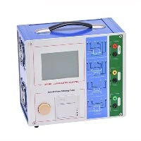
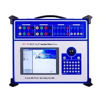
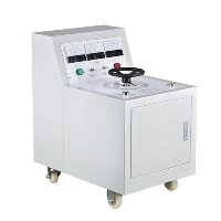
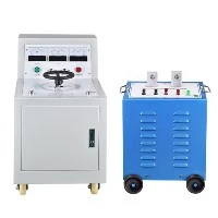
Have you ever witnessed a scene where a construction team blindly excavates the entire street in search of a damaged cable? This' needle in a haystack 'repair method consumes an average of over 48 hours, causing incalculable economic losses and social impacts.
The emergence of modern cable fault testing technology is completely rewriting this situation - it allows power workers to become "line doctors" and achieve precise diagnosis and treatment through pulse signals and intelligent algorithms.
1, Perspective Cable: The Core Principle of Fault Testing
When a cable experiences grounding, short circuit, or disconnection faults, rough measurement of the fault distance is the first step in locking the target. Its core principle is similar to medical ultrasound - emitting energy waves to cables and capturing reflected signals from fault points.
At present, the two mainstream diagnostic techniques each demonstrate their own abilities:
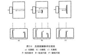
Pulse reflection method (Leda method): Inject high-voltage pulse signals into the cable, and generate reflected waves when the signal encounters impedance change points (fault points). By calculating the time difference (Δ t) between the transmitted and reflected waves and the cable wave velocity (v), the fault distance can be accurately located: fault distance=v × Δ t/2. Modern equipment such as the intelligent flash tester of Wuhan Ultra High Voltage Power Technology Co., Ltd. has achieved automatic waveform analysis with an error control within 0.3%.
Bridge method: Measuring cable resistance or capacitance changes through a balanced bridge, particularly adept at solving high resistance fault problems. The new generation of high-voltage digital bridge integrates computer technology and maintains high accuracy even under complex working conditions.
2, Three Steps to Practical Warfare: From Positioning to Excavation
A complete troubleshooting is like a precise surgical procedure, divided into three stages:
Rough measurement of fault distance: Use a flash tester or bridge tester to determine the approximate range of the fault point (with an error of ± 1 meter)
Path tracking: By using a path signal generator to emit specific frequency signals and cooperating with a receiver to accurately map the underground cable route
Accurate positioning: using acoustic magnetic synchronization method or step voltage method to achieve centimeter level positioning in the target area
Taking the repair of a 10kV cable fault in a certain city as an example: the traditional method requires excavating 12 manhole covers, which takes 72 hours; By using the Wuhan ultra-high voltage TFN FB11 testing system, a rough fault measurement of 64 kilometers of cables can be completed within 5 minutes. With the assistance of precise positioning equipment, the fault can be repaired by excavating only one location, reducing the total time to 8 hours.
3, Equipment Evolution History: From Oscilloscope to AI Diagnosis
Looking back at the development history of technology, cable testing equipment has undergone three revolutions:
1960s-1980s: oscilloscope type flash tester mainly composed of electronic tubes and transistors, with a large volume like a refrigerator
1990s: Storage oscilloscope device controlled by microcontroller, realizing digital waveform storage
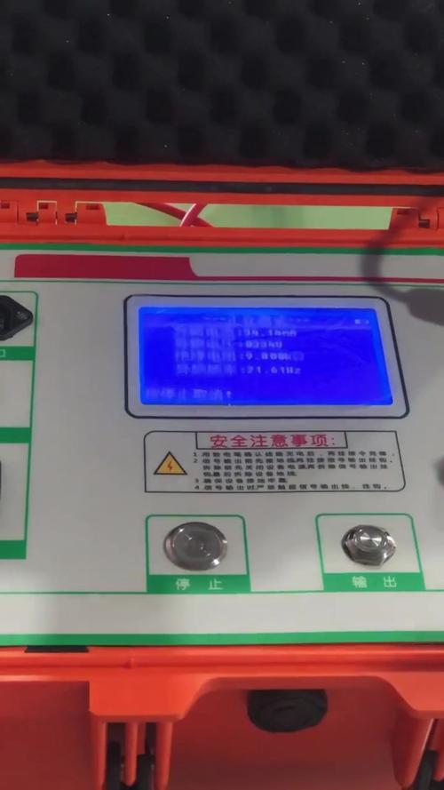
21st century: LCD touch screen devices support intelligent waveform comparison and automatic recognition of fault types
Modern high-end equipment such as cable fault comprehensive testers have three core capabilities:
Dual mode compatibility (low voltage pulse method+high voltage flashover method)
Ultra long standby (built-in power supply supports continuous operation for more than 3 hours)
Intelligent diagnosis (automatically matching cable wave speed parameters, eliminating interference waveforms)
4, Precise grappling technique: a key element for improving positioning accuracy
Even with advanced equipment, these operational details still directly affect the "capture" effect:
Wave speed calibration: There is a significant difference in wave speed between cables of different materials (PVC insulation is about 160m/μ s, XLPE insulation is up to 172m/μ s), and incorrect settings can result in a distance deviation of more than 10%
Connection process: The test line and cable joint must be polished and tightly connected, otherwise the contact resistance will consume weak signals
Anti interference strategy:
Using multiple sampling averaging technique to suppress random noise
Avoid peak electricity consumption testing in power frequency AC mode
Use shielded extension cords to isolate ground stray currents
Especially in complex urban environments, engineers from Wuhan UHV Power Technology Co., Ltd. have developed a unique three-level filtering technology, successfully achieving parallel cable fault location only 3 meters away from the subway in the Beijing CBD area.
5, Future battlefield: integration of intelligence and multifunctionality
With the increasing complexity of urban power grids, the new generation of testing equipment is evolving in three directions:
Cloud platform integration: Real time upload of test data to the cloud, automatic generation of cable health heatmap
Multi technology integration: Integrating functions such as partial discharge detection and dielectric loss analysis into a single device
AR visualization: projecting 3D models of underground cables through augmented reality glasses to guide precise excavation
It is worth noting that data from auxiliary equipment such as loop resistance testers and grounding resistance testers are being incorporated into fault prediction models, forming a complete ecosystem for power cable diagnosis. As a technology leader in the industry, Wuhan UHV's latest ultra-low frequency withstand voltage test device has achieved full process automation of "testing diagnosis repair suggestions".
When a provincial capital city encountered a large area of cable failure caused by rainstorm, the rescue team used equipment with integrated high-voltage flashover method to lock 17 failure points within 2 hours. Behind this efficiency is the perfect combination of modern detection technology and precision instruments - it saves 8 hours of repair time every minute of testing time.
Choosing an excellent set of testing equipment is like equipping a cable maintenance team with "perspective eyes" and "stethoscopes". In today's increasingly important era of power safety, this technology not only safeguards cable safety, but also protects the lights of thousands of households in the city.
Frequently Asked Questions (FAQ)
1. What is the maximum distance that the cable fault tester can detect?
Modern high-end devices such as TFN FB11 support ultra long distance testing of 64 kilometers, meeting the needs of the vast majority of urban power grids.
2. Which is better, pulse reflection method or bridge method?
Each has its own strengths: pulse method is suitable for rapid location of sudden faults; The bridge method is better at analyzing high resistance faults, and a professional team should be equipped with dual-mode equipment.
3. What factors usually cause testing errors?
The main sources of error include deviation in wave velocity setting, poor contact at connection points, and electromagnetic interference. Standardized operation can control the error within 0.5 meters.
4. How to choose suitable testing equipment?
Focus on three major indicators: sampling frequency (determining resolution), battery life (recommended to be more than 3 hours), and protection level (IP54 or above for outdoor use).
5. Why is it necessary to use a high-voltage generator during testing?
For flashover type high resistance faults, it is necessary to artificially create breakdown points using a DC high voltage generator to make the fault characteristics explicit.