

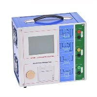
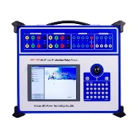
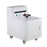

What is the method for testing DC resistance? Wuhan UHV specializes in producing DC resistance testers with a wide range of product options. When looking for a DC resistance tester, choose Wuhan UHV.

1, Measurement purpose
1. Check for short circuits, open circuits, or misconnected wires in the conductive circuit;
2. Check whether the welding points of the winding wires, the connection between the leads and the bushing are good, and whether the tap changer has poor contact.
3. You can also verify whether the wire specifications used in the winding meet the design requirements.
2, Measurement method
1. Current voltage method
The principle is to apply an appropriate amount of DC current to the tested winding, measure the current in the winding and the voltage drop at both ends of the winding, and then calculate the DC resistance of the winding according to Ohm's law. When measuring, the instrument used should not be lower than level 0.5, the ammeter should be selected with a lower internal resistance, the voltmeter should be selected with a higher internal resistance, and the lead wire should have sufficient cross-section. When measuring windings with high inductance, sufficient charging time is also required. The current passing through the winding should be limited to within 20% of the rated current of the winding. The main disadvantage of this method is that it takes a long time to measure accurate values. Because each phase winding can be equivalent to a series circuit of resistance and inductance, after the power is turned on, the current in the inductance gradually increases from zero to the power supply voltage, and then gradually decreases to the steady-state value, requiring a transition process. The length of the transition time depends on the time constant t=L/R of the circuit. Due to the high magnetic permeability of the transformer core, the L value increases significantly, and the DC resistance value of the coil is also very small, resulting in a large time constant t. Generally speaking, the internal resistance of ammeters and voltmeters has a certain impact on the measurement results, and it takes about T=3-5 times the time constant for the current to reach the steady-state value, which means it takes several tens of minutes or even longer to accurately measure the DC resistance.
2. Balanced bridge method
The balanced bridge method uses the principle of bridge balance to measure DC resistance, and commonly used balanced bridge methods include single arm bridge or double arm bridge. This method can directly read data with high accuracy. In the actual measurement of small and medium-sized transformers, the DC bridge method is mostly used. When the resistance value of the tested coil is above 1 Ω, a single arm bridge is generally used for measurement, and below 1 Ω, a double arm bridge is used for measurement. When using a double arm bridge for wiring, the potential pile head of the bridge should be close to the measured resistor, and the current pile head should be connected above the potential pile head. Before measurement, the resistance value of the tested coil should be estimated first. The magnification knob of the bridge should be placed in the appropriate position, and the non tested coil should be short circuited and grounded. Then, the power switch should be turned on to charge. After being fully charged, press the ammeter switch to quickly adjust the measuring arm, so that the ammeter pointer moves towards the zero line in the middle of the ammeter scale for fine adjustment. When the pointer stops steadily at the zero position, record the resistance value. At this time, the resistance value of the tested coil=magnification number multiplied by the resistance value of the measuring arm. After the measurement is completed, release the ammeter button first, and then release the power switch.
3. Simultaneous pressurization method for three-phase windings
Simultaneously applying voltage to the three-phase winding to measure the DC resistance of a transformer is based on Lenz's law, which causes the magnetic fluxes generated by the currents of each phase to cancel each other out in the iron core, resulting in zero synthesized magnetic flux. This reduces the inductance L value and decreases the time constant of the circuit, thereby reducing the time required to measure DC resistance and improving work efficiency. When measuring, factors such as the influence of temperature on the size of winding resistance and the imbalance rate of DC resistance should also be considered. It takes a long time to obtain an accurate value for measuring DC resistance using the voltage drop method, mainly because the current flowing into the coil generates magnetic flux in the high permeability iron core during the change process, resulting in an increase in L. If the magnetic flux is reduced, the L value is also reduced, and the time for the current to change (depending on the time constant) is reduced. Simultaneously applying voltage to the three-phase windings of the transformer and measuring the DC resistance of each phase can achieve this goal. When voltage is applied to the three-phase windings simultaneously, the current flowing into each phase winding increases from zero. According to the right-hand screw rule, the magnetic flux direction generated by the three-phase current in each iron core column is different, and their effects cancel each other out, resulting in the synthesized magnetic flux in the iron core being approximately zero. This greatly reduces the inductance value L, thus reducing the time constant t to its minimum. The transition process of current change during testing is greatly shortened, and a stable current value can be obtained in a short period of time, which can then be used to calculate the DC resistance value of the winding.