



In AC circuits containing resistors, inductors, and capacitors, the voltage and current at both ends of the circuit are generally different phases. If the circuit parameters or power frequency are adjusted to make the current in phase with the power supply voltage, the circuit becomes resistive, and the working state of the circuit is called resonance.

Resonance phenomenon is a specific phenomenon in sinusoidal AC circuits. It is widely used in electronic and communication engineering. But in the power system, resonance may disrupt the normal operation of the system.
Resonance is generally divided into series resonance (also known as variable frequency resonance) and parallel resonance. As the name suggests, series resonance refers to the resonance that occurs in a series circuit, while parallel resonance refers to the resonance that occurs in a parallel circuit.
In a series circuit composed of resistors, inductors, and capacitors. When the capacitive reactance XC is equal to the inductive reactance XL, that is, XC=XL. The phase of voltage U and current I in a circuit is the same, and the circuit exhibits pure resistive behavior, which is called series resonance. When a series resonance occurs in the circuit, the total impedance is minimized and the current will reach its maximum value.
Conditions for series resonance to occur
In order for resonance to occur in a series circuit, certain conditions must be met.
Characteristics of series resonant circuit
When the total impedance value is the smallest and the power supply voltage is constant, the current is the highest, and the circuit is resistive. The voltage on the capacitor or inductor may be higher than the power supply voltage.
Energy changes in a circuit during series resonance
The Q absorbed by the circuit into the power supply is 0. During resonance, energy exchange occurs between the electric and magnetic fields inside the circuit, and the power supply only provides energy to R.
High voltage may damage equipment, and series resonance should be avoided in power systems, which is widely used in radio engineering.
Application of series resonant circuit
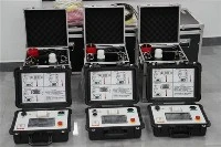
Utilizing series resonance to generate high power frequency voltage, applied in high voltage technology, for conducting withstand voltage tests on power equipment such as transformers. The most effective and direct method for testing the insulation strength of electrical equipment is to effectively detect hazardous concentrated defects in the equipment.
In radios, series resonant circuits are often used to select radio signals, a process called tuning. The following diagram shows its typical circuit.
When various radio waves of different frequencies generate electrical signals of different frequencies on the antenna, they are induced through coil 1L to coil 2L. If the oscillation circuit resonates with a certain signal frequency, the current of the signal in the circuit is the highest, and a voltage CU higher than Q times the voltage of this signal is generated at both ends of the capacitor. For other signals of various frequencies, because resonance does not occur, the current in the circuit is very small, which is suppressed by the circuit. Therefore, capacitor C can be changed to change the resonant frequency of the circuit to select the desired radio signal.