

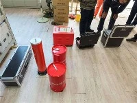

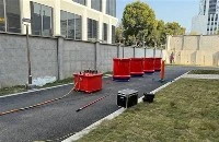
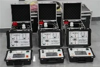
The series resonance under Wuhan UHV can help many power workers conduct various power tests more conveniently.
In high-voltage detection of power systems, resonance technology is mainly divided into two forms: series resonance and parallel resonance. Although the two are based on the same resonance principle, their application scenarios and technical characteristics are significantly different. Many power operation and maintenance personnel often confuse the application scenarios of the two in actual testing, resulting in low detection efficiency and data distortion. This article will provide a detailed analysis of the core differences between series resonance and parallel resonance, as well as their collaborative application techniques, to assist operation and maintenance personnel in accurately selecting detection technologies and building a strong defense line for power grid insulation safety.
1, Core difference: What is the difference between series resonance and parallel resonance?
The core difference between series resonance and parallel resonance lies in the circuit structure, resonance characteristics, and application scenarios. The specific comparison is as follows to clearly distinguish the differences between the two:
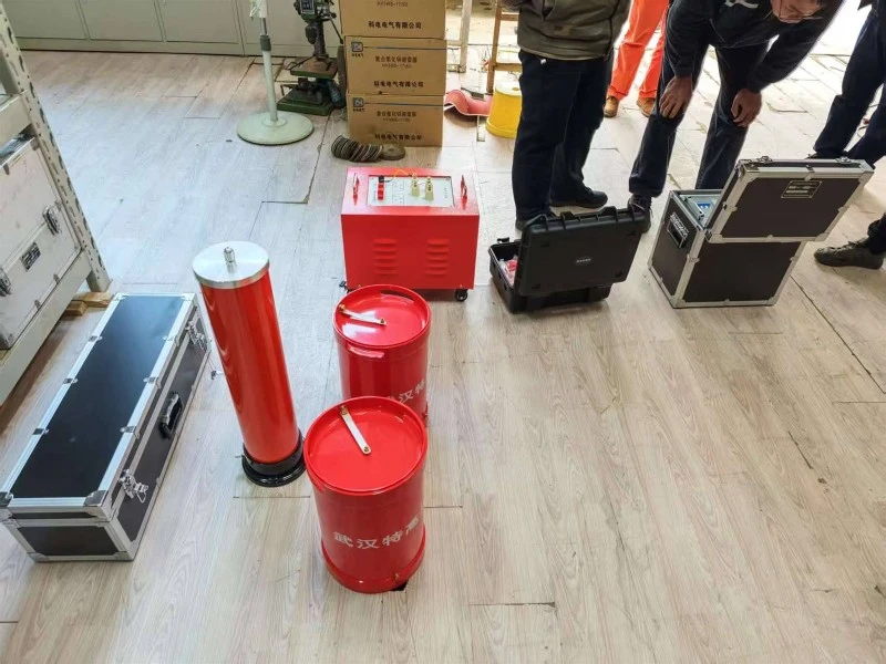
Series resonance: composed of a variable frequency power supply, an excitation transformer, a reactor, a capacitive voltage divider, and a test sample connected in series. The test sample is connected to the series circuit as a capacitive element, and the inductive impedance of the circuit is made equal to the capacitive impedance through frequency modulation to achieve resonance
Parallel resonance: It is composed of a variable frequency power supply, excitation transformer, reactor, and the test object in parallel. The reactor forms a parallel circuit with the test object (capacitor). During resonance, the total impedance of the circuit is maximized, the current is minimized, and stable high voltage is obtained at both ends of the test object.
Resonance characteristic difference series resonance: During resonance, the total impedance of the circuit is minimized and the current is maximized. The voltage at both ends of the test sample is Q times the power supply voltage, and the boosting efficiency is high. It is suitable for testing large capacity capacitive test samples
Parallel resonance: During resonance, the total impedance of the circuit is maximized, the current is minimized, the power burden is small, and the output voltage is stable. It is suitable for detecting small capacity and high impedance test samples, especially for partial discharge detection
Core application scenario difference series resonance: mainly used for AC withstand voltage testing of large capacity capacitive equipment, such as long cables, GIS composite appliances, large transformers, transformers, etc. The core advantages are high efficiency, energy saving, and portability
Parallel resonance: mainly used for insulation detection and partial discharge detection of small capacity equipment, such as lightning arresters, high-voltage insulators, small capacitors, etc. Its core advantages are stable voltage and pure waveform, which can accurately detect small discharge signals
Simply put, series resonance focuses on "high voltage withstand" to solve the problem of detecting large capacity equipment; Parallel resonance focuses on "precise detection" and is suitable for small capacity equipment and hidden defect investigation. The two complement each other and cover the entire scenario of insulation testing for power equipment
2, Collaborative application: How can series and parallel resonance be combined to improve detection performance?
In actual power testing, series resonance and parallel resonance are not used in isolation. The combination of the two can achieve the full process detection of "withstand voltage testing+defect localization", greatly improving the accuracy and efficiency of detection. The core collaborative application scenarios mainly include three types:
1. Full performance testing of lightning arrester As the core equipment for overvoltage protection in the power grid, the insulation performance and discharge characteristics of lightning arrester need to be jointly tested through two resonance technologies
Step 1: Use a parallel resonance device in conjunction with a lightning arrester characteristic tester to conduct partial discharge detection, accurately measure small discharge signals (≤ 5pC) inside the lightning arrester, and identify hidden defects inside
Step 2: Using a series resonant device, conduct an AC withstand voltage test on the lightning arrester to verify its insulation strength. Combined with parallel resonant detection data, comprehensively judge the aging degree and performance status of the lightning arrester.
2. The insulation testing of power cables should take into account both voltage withstand testing and defect localization, and the synergy between the two can achieve full process coverage:
Step 1: Use a series resonant device to conduct an AC withstand voltage test on the cable, apply a high voltage of 1.5 times the rated voltage, verify the overall insulation strength of the cable, and investigate serious insulation defects
Step 2: If abnormalities are found during the withstand voltage test, a parallel resonance device is used in conjunction with a partial discharge testing system to accurately locate hidden defects such as dendritic aging and local damage inside the cable, providing precise basis for fault handling.
3. Comprehensive testing of transformer insulation: The insulation testing of transformer windings should take into account both the withstand voltage strength and local defects. The coordination of series and parallel resonance can improve the comprehensiveness of the testing
4. Step 1: Use a series resonant device to conduct an AC withstand voltage test on the transformer winding, check the overall insulation strength of the winding, and avoid insulation breakdown
4. Step 2: Use a parallel resonance device to carry out partial discharge detection of transformers, investigate small insulation defects between turns and layers inside the windings, warn of faults in advance, and extend the service life of transformers.
3, Practical Standards: Key Considerations for Collaborative Testing
When conducting coordinated testing of series and parallel resonance, the following operating procedures should be followed to ensure testing safety and accurate data
1. Test sequence specification: Partial discharge detection is carried out using parallel resonance first, followed by voltage withstand test using series resonance to avoid interference with partial discharge detection data during voltage withstand test; Before testing, it is necessary to fully discharge the test sample to ensure the accuracy of the test data.
2. Parameter matching setting: Based on the voltage level and capacitance characteristics of the tested equipment, set the output parameters of the two resonant devices reasonably to ensure accurate matching of the resonant point and avoid resonance failure or data distortion caused by parameter mismatch; Series resonance requires the selection of suitable reactors, while parallel resonance requires the adjustment of circuit capacitance to ensure stable output voltage.
3. Safety operation requirements: Both tests must strictly comply with high-voltage safety regulations, ensure reliable equipment grounding, and require operators to wear insulation protective equipment; If there are any abnormalities such as overvoltage, overcurrent, or flashover during the experiment, immediately reduce the voltage and stop the machine. After troubleshooting, continue the experiment; After the experiment, fully discharge the test sample and equipment to avoid the risk of electric shock.
4. Data linkage analysis: Detailed recording of all data from two resonance tests, establishment of equipment detection files, trend analysis based on historical data, comprehensive judgment of equipment insulation status changes, avoiding misjudgment caused by single test data, and providing scientific support for equipment maintenance plans.
4, Equipment selection and maintenance: the basic guarantee for collaborative applications
1. Collaborative selection skills: If the main focus is on conducting withstand voltage tests on large capacity equipment, priority should be given to selecting the Wuhan UHV series series series resonant device, paired with a basic parallel resonant device, to meet the needs of partial discharge detection. If the emphasis is on scientific research or high-precision detection, choose a series resonant device with high Q value and wide frequency range, paired with a high-precision parallel resonant device, to ensure accurate detection data. Priority should be given to selecting equipment from the same manufacturer to ensure good compatibility between devices, facilitating data linkage and collaborative operation, while enjoying unified after-sales technical support.
2. Key points of collaborative maintenance: Regularly clean and perform insulation testing on the reactors and capacitive dividers of the two resonant devices to avoid insulation aging and dust accumulation that may affect testing performance. Regularly calibrate the variable frequency power supply and voltage and current measurement module to ensure consistent measurement accuracy between the two devices and avoid data deviation. When not in use for a long time, place the equipment in a dry and ventilated environment, turn on the power regularly, check the equipment status, and avoid circuit moisture and component aging. Clean the surface stains of the equipment in a timely manner after the experiment, check the connection of the circuit, keep maintenance records, and extend the service life of the equipment
FAQ
Q1: How to quickly determine whether a certain type of equipment is suitable for series or parallel resonance detection?
A1: Focus on the capacitance and impedance of the test sample: For capacitive devices with large capacity and small impedance (such as long cables and GIS), series resonance should be prioritized; Small capacity and high impedance equipment (such as lightning arresters and insulators) should prioritize parallel resonance; For partial discharge detection, parallel resonance should be prioritized.
Q2: Why do we need to perform partial discharge detection first when testing series and parallel resonance?
A2: Because the withstand voltage test of series resonance will have a certain impact on the insulation of the test sample, if the withstand voltage test is conducted first, it may expand the hidden defects inside the test sample, resulting in distortion of partial discharge detection data; First, perform partial discharge testing to accurately capture the original insulation state of the test sample, and then conduct a withstand voltage test to verify the insulation strength, ensuring the reliability of the testing results.
Q3: How to deal with abnormal partial discharge signals in parallel resonance tests?
A3: Immediately reduce the pressure and stop the machine, check whether the surface of the test sample is dirty or damp, whether the wiring is loose or poorly connected; If external factors are excluded, it indicates that there are hidden defects inside the test sample. It is necessary to combine the results of the series resonance withstand voltage test to further locate the type of defect and carry out maintenance or replacement in a timely manner.
Q4: Can the reactors of the two resonant devices be used interchangeably?
A4: Not recommended for general use. The series resonant reactor is mainly used to increase the output voltage, and the parameters need to be matched with the capacitance of the test sample; Parallel resonant reactors are mainly used to stabilize circuit impedance, and their parameter design is different from that of series resonant reactors. General use can lead to the inability to find resonance points, data distortion, and even damage to equipment.
Q5: The higher the Q value of the resonant device, the better the detection effect?
A5: Higher is not necessarily better. A high Q value can lead to a decrease in circuit stability, which can easily result in resonance point drift and voltage fluctuations; If the Q value is too low, it will reduce the boost efficiency and increase the demand for power capacity. Normally, the series resonance Q value is controlled between 20-50, and the parallel resonance Q value is controlled between 10-30, which can balance boost efficiency and detection stability.