



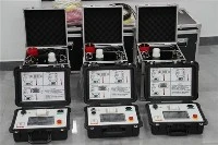
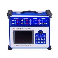
Wuhan UHV specializes in producing series resonance (also known as series resonance test equipment). Next, we will share with you the principles of series resonance and parallel resonance, as well as why parallel resonance has a high current.
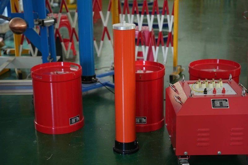
Principles of series resonance and parallel resonance
In a series circuit of resistors, inductors, and capacitors, the phenomenon where the terminal voltage of the circuit is in phase with the total current of the circuit is called series resonance. A series resonant circuit is purely resistive, with terminal voltage and total current in phase. At this time, the impedance is small and the current is large, which may generate high voltages on the inductance and capacitance that are many times greater than the power supply voltage. Therefore, series resonance is also known as voltage resonance.
In a circuit where an inductor is connected in parallel with a capacitor, the phenomenon of parallel resonance occurs where the terminal voltage of the parallel circuit is in phase with the total current of the circuit. The total impedance of a parallel resonant circuit is relatively large, resulting in a smaller total current. However, for each branch, its current may be much larger than the total current, hence current resonance is also known as current resonance.
The reason for the large parallel resonance current
Parallel resonance is a structural branch of the series resonance test device used for insulation performance testing of electrical equipment. "Parallel" is a connection method in which the circuit inductance and capacitance during resonance are equal and cancel each other out. The circuit is in a pure resistance load state, where the resistance in the circuit is minimized and the current is maximized. According to Ohm's law U=IR, it can be concluded that when a series resonant circuit is connected in parallel, the resistance in the circuit is minimized, the voltage remains constant, and the current is maximized.