

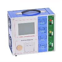

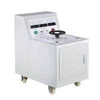
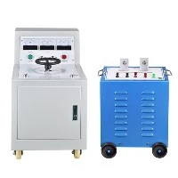
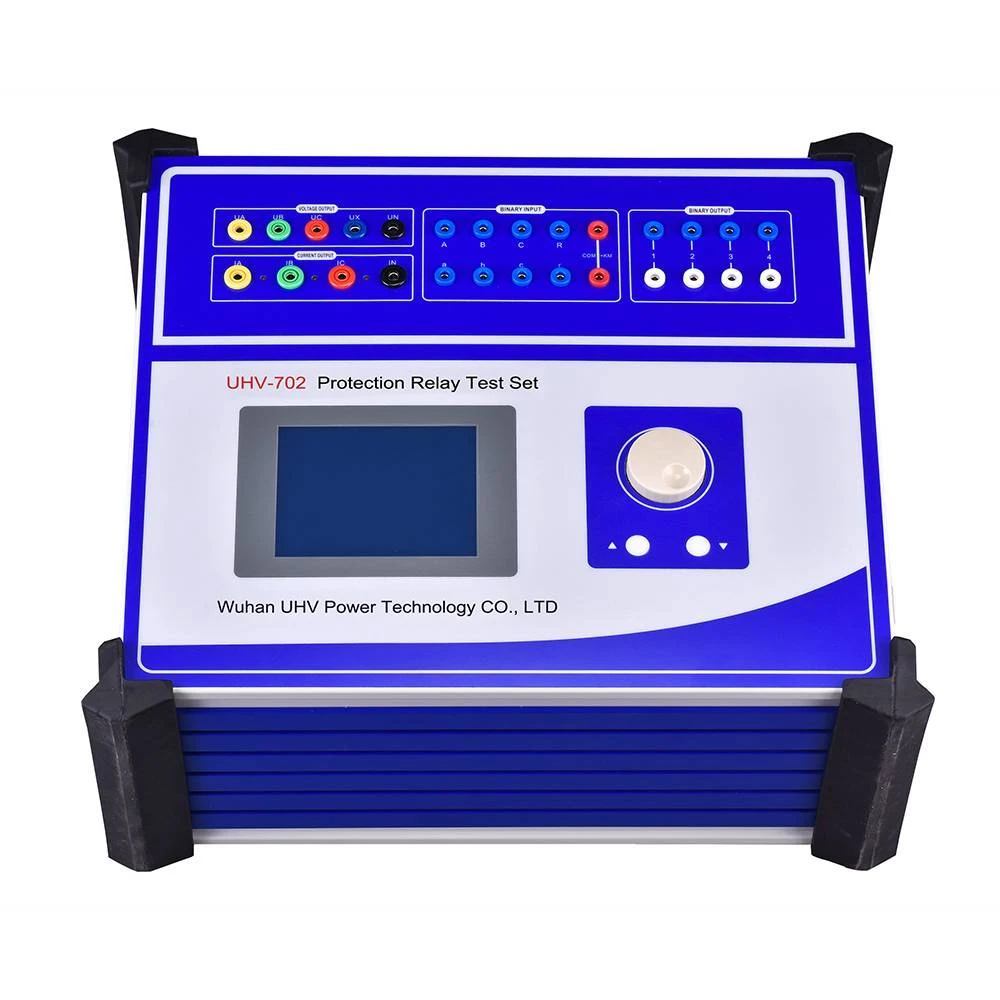
The Secondary Current Injection Test Set under Wuhan UHV can help many power workers conduct various power tests more conveniently.
Primary current and secondary current are core concepts in transformers (or instrument transformers). Their main differences lie in the winding they flow through, their function, and the relationship between them:
1.Winding They Flow Through:
Primary Current (I₁): The current flowing through the transformer's primary winding (input winding). This winding is connected to the power source (AC supply).
Secondary Current (I₂): The current flowing through the transformer's secondary winding (output winding). This winding is connected to the load (the electrical device consuming power).
2.Function and Direction:
Primary Current (I₁): This is the current drawn from the power source by the transformer. It establishes the alternating magnetic field in the transformer's core. It can be seen as the input current.
Secondary Current (I₂): This is the current supplied to the load, induced by the alternating magnetic field. It can be seen as the output current. Its flow direction depends on the load's requirements.
3.Relationship (Ideal Transformer):
This is the most crucial point for understanding the difference. In an ideal transformer (ignoring all losses):
Voltage Relationship: The ratio of primary voltage (V₁) to secondary voltage (V₂) equals the ratio of primary turns (N₁) to secondary turns (N₂): V₁ / V₂ = N₁ / N₂
Current Relationship: The ratio of primary current (I₁) to secondary current (I₂) equals the inverse of the ratio of secondary turns (N₂) to primary turns (N₁): I₁ / I₂ = N₂ / N₁ (or I₁ * N₁ = I₂ * N₂ - Ampere-turn balance).
Power Conservation: Ignoring losses, input power equals output power: V₁ * I₁ ≈ V₂ * I₂ (for the real power component).
4.Core Relationship Summary:
The turns ratio determines the voltage ratio and the current ratio.
Step-up Transformer (N₂ > N₁): V₂ > V₁ (output voltage increases), I₂ < I₁ (output current is less than input current).
Step-down Transformer (N₂ < N₁): V₂ < V₁ (output voltage decreases), I₂ > I₁ (output current is greater than input current).
Isolation Transformer (N₂ ≈ N₁): V₂ ≈ V₁, I₂ ≈ I₁ (primarily used for isolation, not changing voltage/current).
5.Load Influence:
Secondary Current (I₂) is determined solely by the load. The greater the power demanded by the load (or the lower its equivalent resistance), the larger the secondary current.
Primary Current (I₁) responds to changes in the secondary current. According to I₁ / I₂ = N₂ / N₁ (or I₁ * N₁ = I₂ * N₂), when the secondary current increases due to a heavier load, the primary current must also increase correspondingly to satisfy power conservation and ampere-turn balance. The change in secondary current is the "cause"; the change in primary current is the "effect". Under no-load conditions (secondary current = 0), the primary current is very small (only the magnetizing current needed to establish the magnetic field).
6.Phase Relationship (Ideal Transformer):
In an ideal transformer, the primary current and secondary current are 180 degrees out of phase. This is because the magnetic flux produced by the secondary current always opposes the flux produced by the primary current (Lenz's Law), working to maintain the main flux essentially constant.