

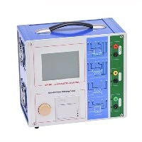
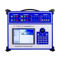
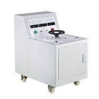
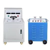
The application of LC series resonance? Wuhan UHV specializes in the production of series resonance, with a wide range of product selection and professional electrical testing. To find series resonance, choose Wuhan UHV.

Disadvantages caused by resonance
Resonance is mainly generated by high-power converter equipment (including chemical electrolytic rectification equipment) and other nonlinear loads called harmonic sources. The resonance generated by harmonic sources not only endangers the power grid and other power users, but also endangers itself. Therefore, harmonic control is necessary and has practical economic benefits. Example: A certain chemical plant is powered by Haocun Station. Three sets of 10.8Mvar parallel capacitors are installed in the station, which are connected in series with reactors with reactance rates of 4.5%, 7%, and 12%, respectively. They are used to limit the amplification of fifth and above, fourth and above, and third and above harmonics, and to form incomplete vibration filtering for the fifth, fourth, and third harmonics, respectively. After being put into operation, the capacitors experienced severe overload and abnormal noise. Some capacitors bulged shortly after being put into operation. Later testing found that the harmonic voltage of the bus and the harmonic current of the capacitor circuit exceeded the standard. To prevent further damage to the equipment, all 10.8Mvar capacitors were taken out of operation. Further testing of Hecun Station shows that the harmonics mainly come from a certain chemical plant, with high harmonic content and a wide frequency spectrum range (the lowest being secondary). After multiple investigations and tests by professional personnel on the wiring, equipment configuration, and operation of the power distribution system in the chemical plant, the situation has been basically grasped, and the causes of the second and higher harmonic generation have been analyzed, and effective governance plans have been formulated.
Application of series resonance
frequency selection
The frequency selection characteristics of series resonant circuits are used in the tuning circuit of radio receivers to select signals. The receiver antenna receives signals of various frequencies and induces corresponding electromotive forces in the series resonant circuit. At this point, changing the value of the "variable capacitor" adjusts the desired signal frequency to a series resonant state. The impedance of the circuit is minimized, and the current at that frequency is maximized. The voltage at this frequency is also highest at both ends of the variable capacitor. However, signals at other frequencies are attenuated due to the absence of resonance, so the current in the circuit is very small, thus playing a role in selecting signals and suppressing interference.
filtering
If a trapezoidal wave or rectangular wave is converted into a sine signal, high-order harmonics must be filtered out. A simple method is to use Fourier series expansion of the trapezoidal wave or rectangular wave to obtain an infinite number of odd harmonic AC components, and the maximum value of each harmonic decreases rapidly with the increase of harmonic order. It can be seen that as long as the maximum third and fifth harmonics in the trapezoidal wave or rectangular wave are filtered out, a relatively standard sine wave can be obtained. Resonance occurs in the fundamental harmonic of rectangular waves, which means that the filtering circuit knows from the characteristics of resonance that when series resonance occurs with AC power at a certain frequency, the impedance of the AC power at that frequency is the smallest, while when parallel resonance occurs, the impedance of the AC motor at that frequency is the largest.
feature
The voltage waveform is good. Series resonance is a voltage withstand state that is close to full resonance. When the weak point of the insulation in the test sample is broken down, the circuit loses resonance conditions. Therefore, the short-circuit current immediately drops to one tenth of the test current, the high voltage disappears immediately, and the arc is extinguished immediately. However, using traditional testing methods, the short-circuit current will be very large, and the test sample may form series resonance with the test transformer, resulting in significant overvoltage, which is very detrimental to the test sample and testing equipment. Small in size and lightweight, suitable for on-site use. Due to the significant reduction in capacity and weight of the test power supply, as well as the elimination of bulky voltage regulators, it is easier to transport and solve on-site test power supply problems. Easy to connect, simple to operate, voltage and frequency adjustment can be continuously and finely adjusted, with high resolution and good stability.
10kV test method and principle
With the continuous development of the power system and the increasing capacity and voltage levels of the system, the testing methods for electrical equipment need to be improved. Because according to the testing regulations and preventive testing regulations for power equipment, it is necessary to conduct AC withstand voltage tests on electrical equipment, which requires a high voltage source. The previous method of obtaining high voltage was to use a large ratio voltage transformer for power frequency boosting. Using this boosting method, due to the large and bulky size of the equipment used, a crane must be used for movement and installation, making on-site testing extremely inconvenient. A new boosting device designed based on the principle of series resonance not only solves the problem of clumsy testing equipment, but also completes the withstand voltage test in electrical equipment well. To test the same equipment with a series resonant boost device, only inductors, capacitors, and some small auxiliary equipment are needed. During the experiment, each group of capacitors is connected in parallel and then connected in series with an inductor. The test project can be completed by assembling them through a modular overlapping method. The cost of this test device is very similar to that of a large ratio voltage transformer, less than 100000 yuan. However, the application of a series resonant boosting device can save excessive expenses in each test and avoid difficulties in the test. So the series resonant boost device has good economic and practical value, and has begun to be promoted in engineering tests.
Due to the fact that the parameters of the test sample can affect the characteristics of the original series circuit, the relationship between Cx and C, Co, and L should be analyzed and considered to induce resonance in the circuit. Adjusting L and C can bring the circuit to the resonance point. It can be seen that although the series resonant test system solves the disadvantage of clumsy equipment, it is necessary to calculate the values of L and C in advance based on the resonance principle when testing different devices. By using the application device of series resonance, it is convenient to conduct transformer AC withstand voltage tests. However, the difference is that when the transformer has a large capacitance to ground, its capacitance value needs to be included in the tuning, while when the capacitance to ground is very small, only the resonance condition of the instrument itself needs to be considered during tuning. Moreover, there are significant differences in the parameter characteristics between the primary and secondary sides of the transformer. Therefore, it is necessary to accurately calculate and design the L and C values taken in the testing system.