

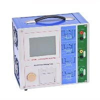
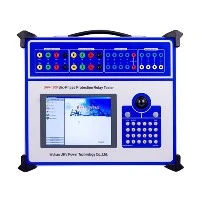
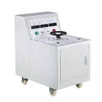
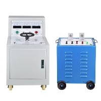
The cable fault tester under Wuhan UHV can help many power workers conduct various power tests more conveniently.

1. Low-Voltage Pulse Method / Time Domain Reflectometry (TDR)
Principle: Injects a low-voltage pulse into the cable. Reflections occur at impedance discontinuities (e.g., faults, joints, open circuits). Distance is calculated using the time delay and wave propagation velocity.
Applications:
Highly accurate for open-circuit faults.
Effective for low-resistance faults (short circuits, grounds with impedance < ~1/5 of cable's characteristic impedance).
Measures cable length, locates joints.
Pros: Safe (low voltage), fast, intuitive, high precision (especially for opens).
Cons: Ineffective for high-resistance faults (weak/no reflection).
2. High-Voltage Impulse (Surge) Method / Arc Reflection Method
Principle: Applies high-voltage DC or surge pulses to breakdown high-resistance/flashing faults, creating a temporary low-resistance arc at the fault. Uses two effects for pinpointing:
Acoustic wave ("bang" from discharge).
Electromagnetic pulse (EM field from arc).
Pinpointing Techniques:
Acoustic-Magnetic Synchronization:
Uses a surge generator to create periodic discharges.
An acoustic-magnetic receiver detects both sound and EM pulses.
Fault location is where sound intensity peaks and sound/EM pulses are synchronized.
Acoustic Method (standalone): Less precise; relies only on discharge sound.
Pros: Most effective for high-resistance & flashing faults.
Cons: Requires high-voltage equipment, complex operation, safety risks, noise-sensitive.
3. Bridge Methods (e.g., Murray/Varley Loop)
Principle: Uses Wheatstone bridge theory. Compares resistance ratios between a faulty conductor and a "good" reference conductor to calculate distance.
Pros: Simple equipment (historically), moderate accuracy for low-resistance faults.
Cons: Requires a "good" reference conductor & remote cable end bridging; ineffective for high-R faults; largely superseded by TDR.
4. Secondary Impulse Method
Principle: Combines HV surge and TDR. A low-voltage pulse is injected during the HV-induced arc (when fault temporarily becomes low-R). Compares pre-arc and post-arc waveforms to identify fault distance.
Pros: High accuracy for high-R faults, intuitive waveform comparison, reduces need for acoustic pinpointing.
Cons: Complex/expensive equipment, requires operator expertise.
5. Time Domain Reflectometry (TDR)
Principle: Standard for telecom/copper/low-voltage power cables. Analyzes reflections of high-speed pulses to locate opens, shorts, or impedance mismatches.
Applications: Telecom/coaxial/twisted-pair cables; low-voltage power cables.
6. Optical Time Domain Reflectometer (OTDR)
Principle: For fiber optic cables. Injects light pulses and analyzes backscattered/reflected light to measure length, loss, breaks, or splice points.
Applications: Fiber breaks, high-loss points, splice loss evaluation.