


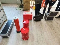


The series resonance under Wuhan UHV can help many power workers conduct various power tests more conveniently.

What is "Automatic Tuning"? How Does It Work?
The core purpose of "automatic tuning" is to allow a circuit (such as an LC resonant circuit) to automatically match its resonant frequency to the frequency of the input signal or the required operating frequency of the system, thereby achieving maximum energy transfer, highest efficiency, or optimal signal quality.
Working Principle (Using the most common Phase-Locked Loop (PLL) as an example):
1.Phase Detection: The system continuously compares the phase difference between the input signal (or reference signal) and the output signal generated by a Voltage-Controlled Oscillator (VCO).
2.Generate Error Voltage: The phase detector converts this phase difference into a DC error voltage. The greater the phase difference, the greater the absolute value of the error voltage.
3.Low-Pass Filtering: This error voltage is passed through a low-pass filter to become a smooth DC control voltage. This filter is crucial as it determines the system's response speed and stability.
4.Control the Oscillator: The filtered DC control voltage is applied to the VCO, changing its oscillation frequency. The rule is: increased control voltage raises the VCO frequency; decreased control voltage lowers the VCO frequency.
5.Locking: This is a negative feedback process. The system continuously adjusts the VCO's frequency until the phase difference between the output signal and the input signal is zero (or constant). At this point, the VCO's frequency is considered fully "locked" to the input frequency, meaning "automatic tuning" is complete.
What Should I Do If I Can't Find the Resonance Point? (Troubleshooting Guide)
If an automatic tuning system cannot find the resonance point, it usually manifests as the system failing to lock, very low efficiency, very low output power, or even protective shutdown of the equipment. Please follow these steps to troubleshoot:
1. Check Hardware Connections and Components
Basic Checks: Ensure all cables, terminals, coils, and antennas are connected securely, without cold solder joints, shorts, or open circuits. A loose connection can ruin the entire tuning process.
Are Component Values Suitable? Confirm whether your inductor (L) and capacitor (C) values are within the theoretical design range. For example, if your signal frequency is 1MHz, but the theoretical resonant point of your LC network is below 100kHz, you naturally cannot tune to the target frequency.
Are Components Damaged?
Capacitors: Especially variable capacitors (varactor diodes) or vacuum capacitors might be breakdown, short-circuited, or stuck.
Inductors: Coils might be deformed, have shorted turns, or be open.
Power Devices: In power amplifiers, tubes or transistors may be aged or underperforming.
2. Analyze the Signal and Environment
Is the Signal Strength Too Weak? The automatic tuning circuit requires a strong enough signal to detect the phase difference or power value. If the input signal is too weak, the detection circuit may not work properly, causing the system to "blindly tune." Try increasing the power or amplitude of the signal source.
Is the Interference Too Strong? Is there strong electromagnetic interference (EMI) around? Interference signals might drown out the target signal you need to tune to, causing the detection circuit to misjudge.
Is the Load Changing Rapidly or Mismatched? The resonant frequency is closely related to the load. If the load (e.g., an antenna, workpiece) changes drastically during the tuning process (e.g., plasma impedance changes sharply before and after ignition), the tuning system may not be able to keep up and lose lock. Ensure the load is in a normal and stable operating state.
3. Examine the Tuning System Itself
Insufficient Tuning Range: This is one of the most common reasons. The frequency adjustment range of your variable capacitor or VCO might not cover the actual resonance point. Solution: Recalculate the required capacitance/inductance variation range and replace the tuning components with ones that have a wider range.
Tuning Step or Speed Problem:
Step Size Too Large: If the system is digitally controlled, and the tuning step is set too large, it might "step over" the resonance point and fail to find it. Try reducing the tuning step size for a finer search.
Speed Too Fast: The system adjustment speed is too fast, while the feedback loop response is slow, causing the system to oscillate (swing back and forth around the resonance point) instead of stabilizing and locking. The parameters of the control loop (e.g., PID parameters) need to be optimized.
Faulty Detection Circuit: The phase detection circuit, power detection circuit, or ADC sampling circuit might itself be faulty, providing an erroneous error signal that leads to incorrect tuning direction.