


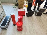


Principle of series resonance test device? Wuhan UHV specializes in the production of series resonance, with a wide range of product selection and professional electrical testing. To find series resonance, choose Wuhan UHV.

The series resonance test device, also known as series resonance, can be divided into frequency modulation and induction modulation. The variable frequency series resonant device is generally composed of a variable frequency power supply, an excitation transformer, a reactor, and a capacitive voltage divider. The capacitor and reactor of the test sample form a series resonant connection, and the voltage divider is connected in parallel to the test sample to measure the resonant voltage on the test sample and provide an overvoltage protection signal.
We know that at the circuit frequency, resonance occurs in the circuit, and the voltage on the test sample is Q times the output voltage of the excitation transformer high voltage end. Q is the system quality factor, which is the voltage resonance multiple, generally ranging from tens to hundreds or more. First, adjust the output frequency of the variable frequency power supply to induce series resonance in the circuit, and then adjust the output voltage of the variable frequency power supply under the condition of circuit resonance to achieve the test value of the sample voltage. Due to the resonance of the circuit, a smaller output voltage of the variable frequency power supply can generate a higher test voltage on the test sample CX.
Common fault phenomena of series resonance test device
1. Flashing phenomenon of series resonance test device
When destructive discharge occurs along the solid insulation surface in a gas or liquid dielectric, it is called flashover. Flashover phenomenon refers to the phenomenon where the breakdown voltage discharges along the surface of a solid insulator when the gas or liquid dielectric surrounding the insulator is broken down. The voltage at which flashover occurs during discharge is called the flashover voltage. After flashover of the insulator, the voltage between the electrodes rapidly drops to zero or close to zero. Sparks or arcs in the flashover channel cause local overheating of the insulation surface, resulting in carbonization and damage to the surface insulation.
The common occurrence is flashover along the interface between gas and solid dielectric. The destructive discharge along the surface of the insulator string and the surface of the bushing is called flashover. The term flashover is only applicable to discharge phenomena under special conditions.
2. Discharge phenomenon of series resonance test device
The discharge phenomenon is a relatively general concept, generally referring to the transition of insulating materials from an insulating state to a conductive state under the action of an electric field. This jump phenomenon may occur in a "through state" between the electrodes, where the insulation material is completely short circuited and damaged. At this time, the voltage between the electrodes rapidly drops to a very low or near zero value, which is called destructive discharge; The jump phenomenon may also occur in local areas between electrodes, causing the insulation material to be locally short circuited while the rest of the area still has good insulation performance, and the voltage between electrodes can still maintain a certain value, which is called partial discharge.
Destructive discharge and partial discharge can be used in all dielectrics and their combinations, however, discharges occurring in different dielectrics and their combinations have special names. The destructive discharge that occurs between electrodes in a gas or liquid dielectric is called spark discharge, such as the destructive discharge that occurs in air gaps or oil gaps, which should be more precise as spark discharge.
When destructive discharge occurs in a solid dielectric, it is called breakdown. When breakdown occurs, traces are left in the solid dielectric, causing the solid dielectric to permanently lose its insulation properties. When the insulation cardboard breaks down, a hole will be left on the cardboard.