

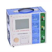

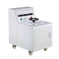
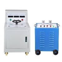
The special frequency determined by the values of resistance, capacitance, and inductance refers to resonance in AC circuits. The resonance frequency point occurs where the inductance reactance of the inductor is equal to the capacitance reactance of the frequency change.
The most important circuit used in series resonant circuits for electrical and electronic circuits can be found in various forms such as noise filters, AC power filters, and broadcast and television tuning circuits. A very selective tuning circuit produces receiving channels of different frequencies. The resonance of a series RLC circuit occurs when the inductance and capacitance reactance are equal in size, but cancel each other out due to a phase difference of 180 degrees.
The current series resonant circuit diagram shows that the amplitude of the circuit current increases from bottom to top and the frequency increases from left to right. The resonant frequency formula shows that holding such a simple series LC circuit, the self peak value of a simple parallel LC circuit can be seen at the planned frequency point of 157.9 Hz. Recent analysis suggests that the expected resonant point is 159.55 Hz.
When the power frequency approaches resonance, the total impedance of the series LC circuit tends to zero. Due to high current flow and a large number of individual component impedances, the individual components of a series LC circuit can form extremely high voltages during resonance. Dangerous high voltage may be generated between capacitors and inductors.

Parallel resonance
The resonance of parallel RLC circuits is much more complex than series resonance. There are three methods for defining the resonant frequency, which converge to the same expression for the series resonant frequency with lower resistance in the circuit. In many ways, parallel resonant circuits are identical to series resonant circuits because they are both ternary networks that contain two reactive elements, making them second-order circuits. They are all affected by changes in power frequency and have a frequency point at which their two reactive elements cancel each other out, thereby affecting the characteristics of the circuit.
When the power frequency approaches resonance, the total impedance of the parallel LC circuit tends to infinity. When the total impedance increases to infinity and the capacitive and inductive reactance are equal, the fuel tank circuit does not draw current from the AC power source.
Resonance in Series Parallel Circuits
In simple resistive or reactive power circuits, sharp changes in impedance will be manifested at the resonant frequency.