

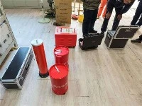


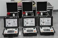
The on-site cable testing device is based on the principle of variable frequency series resonance (also known as cable AC withstand voltage test). They are built-in modules designed specifically for on-site testing needs. A simple and powerful reactor has the possibility of series and parallel connection, and more units can optimize the system's adaptability to load capacitance. The transportation and control of containers make transportation and trucking possible around the world. Air to air, dedicated casing available.

Compared to other on-site testing techniques such as 0, 1 Hz, DC, or oscillation, resonant testing groups generate voltage stresses similar to operating conditions. This provides more evidence for the test results and is the preferred on-site testing method.
Partial discharge measurement
The experiment may be accompanied by partial discharge measurements. Can a static frequency converter generate only 4 switching pulses per cycle without interference in PD mode? Alternatively, if an appropriate measurement system is used, can switch pulses be suppressed.
environmental conditions
The design of the experimental device requires that weather conditions around the world be conducted under good conditions on land or shore.
Reactor coil
The core reactor is immersed in oil and equipped with an A-type sealed cylinder. Two units can be stacked to increase the output voltage of the system, and the reactor is a lightweight design with a fixed inductance.
Excitation transformer
A tank transformer with lightning arrester protection and automatic grounding is a resonant circuit used for excitation, and voltage and power are corresponding system requirements.
frequency converter
The square wave voltage generated by the converter has an adjustable frequency between 15 and 250 Hz, which supplies power to the excitation transformer. Due to the principle of series resonance, the test voltage is an ideal sine wave waveform, and the system is tuned by changing the frequency to generate resonance.
Control unit/voltage measurement
The control unit and touch screen are integrated with the inverter casing, achieving automatic and manual testing. A separate computer stores measurement data and generates test protocols. The high voltage is measured jointly by a built-in peak voltmeter and a high voltage divider, and works simultaneously with the base load capacitor.