

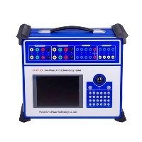
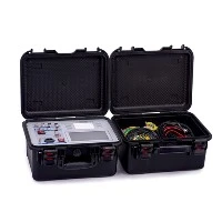
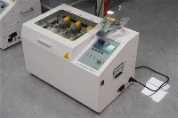
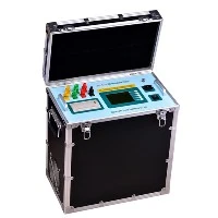
A dielectric loss factor tester is a high-precision electronic instrument designed for field measurement of the dielectric loss factor (tanδ) and capacitance (Cx) of insulation materials (dielectrics) in electrical equipment (e.g., transformers, instrument transformers, bushings, capacitors, cables). Its core feature is the use of heterodyne frequency technology to effectively suppress on-site power-frequency electromagnetic interference.
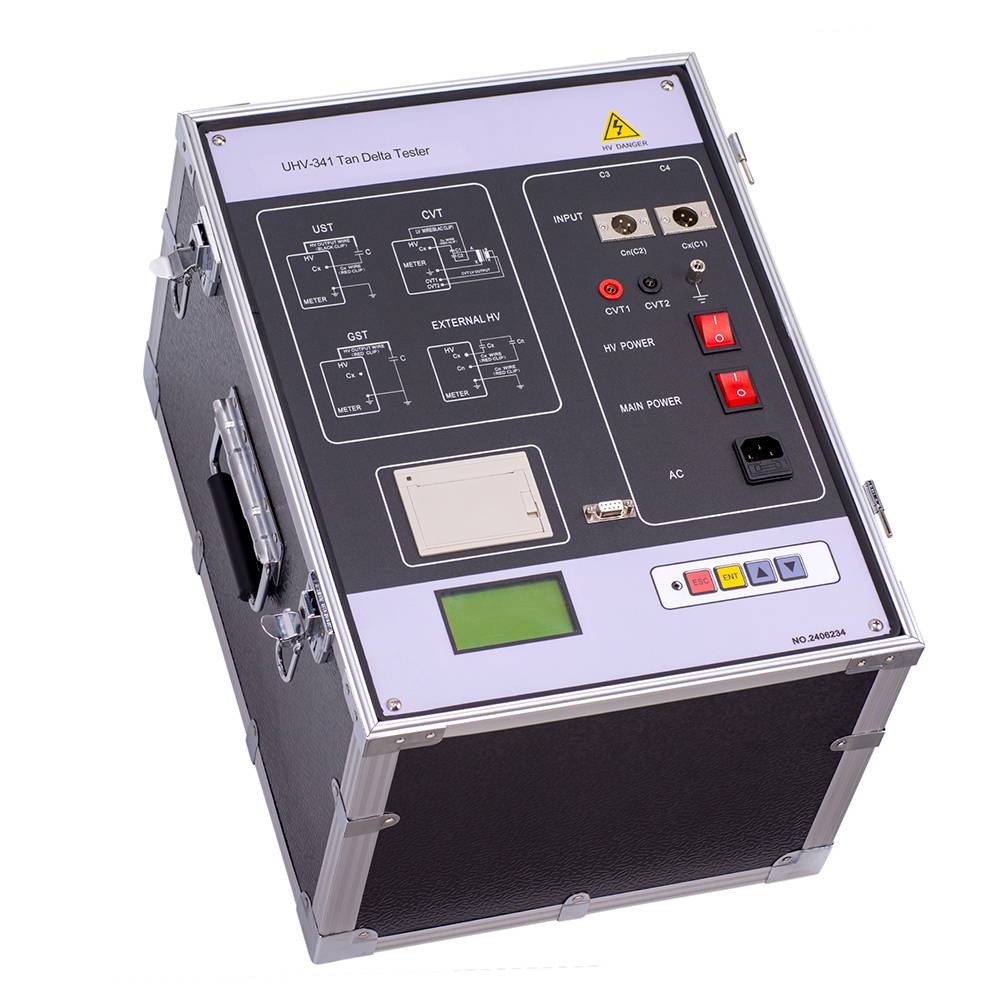
Key Concepts Explained:
1.Dielectric Loss:
Refers to energy loss in insulating materials under AC electric fields due to conductance, polarization, and partial discharge. This energy converts to heat.
The primary parameter for quantifying dielectric loss is the Dielectric Loss Factor, denoted as tanδ ("tangent delta"). It represents the ratio of resistive power loss to reactive capacitive power in the dielectric. A lower tanδ indicates lower losses and better insulation performance.
2.Purpose of Dielectric Loss Testing:
Assess Insulation Condition: tanδ is highly sensitive to overall insulation aging, moisture ingress, or degradation. Deterioration typically causes a significant increase in tanδ.
Diagnose Defects: Detects localized defects (e.g., partial discharge, delamination, cracks) or distributed defects (e.g., overall moisture absorption, aging).
Preventive Maintenance: A critical test during equipment commissioning and routine maintenance to determine operational safety.
3."Heterodyne" Technology & Its Necessity:
Problem: Strong electromagnetic interference from 50Hz/60Hz power frequency and its harmonics in substations distorts measurements, making traditional power-frequency testers unreliable or unusable.
Solution: "Heterodyne" technology solves this by using test frequencies different from 50Hz/60Hz (typically near integer multiples of power frequency but avoiding harmonic points).
Common Heterodyne Modes:
Dual-Frequency Method (Most Common): Automatically measures at two distinct frequencies (e.g., 45Hz/55Hz or 55Hz/65Hz) in quick succession. Algorithms then compute equivalent power-frequency tanδ and Cx. Frequencies are usually symmetric around the power frequency.
Variable-Frequency Method: Scans or selects the least noisy frequency within a broad range (e.g., 30Hz–300Hz), then converts results to power-frequency equivalents using mathematical models.
Anti-Interference Principle:
Power-frequency interference peaks at specific frequencies (50Hz, 100Hz, 150Hz...).
Heterodyne testing avoids these peaks, selecting quieter frequencies.
Digital signal processing (e.g., Fourier transforms) extracts test signals while suppressing noise.
The Dual-Frequency Method leverages interference correlation between close frequencies to cancel noise.