

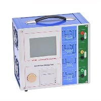
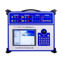
A transformer on load tap charger tester is a core instrument used in power systems to detect and diagnose the condition of on-load tap-changers.

It performs precise measurements to effectively assess the mechanical and electrical performance of an on-load tap-changer without the need for tank lifting or oil drainage. The key parameters it measures can be categorized as follows:
1, Core Timing Parameters (The Most Critical)
These parameters directly reflect the operating sequence of the switching mechanism and the health of the mechanical system.
1.Transition Time
Definition: The total time elapsed from when the diverter switch begins to operate (main contacts separate) until the action is completed (final contacts close).
Significance: This is the most important indicator of the mechanical performance of the switching system. Excessively long time often suggests mechanisms are stuck, poorly lubricated, or springs are fatigued; an excessively short time may indicate excessive mechanical impact.
2.Bridging Time (Overlap Time)
Definition: The duration during the switching process when the transition resistor bridges two taps. This is when the moving contact simultaneously touches two fixed contacts.
Significance: Extremely critical. Too short a time can cause the transition resistor to withstand huge short-circuit currents and energy, leading to burnout. Too long a time can cause the resistor to overheat due to prolonged energization. It must strictly comply with the manufacturer's design value.
3.Three-Phase Synchronization (Non-synchronization Time)
Definition: The difference between the longest transition time and the shortest transition time among phases A, B, and C.
Significance: Reflects the synchronization performance of the mechanical linkages for phase-separated switching mechanisms. Poor synchronization can lead to three-phase current imbalance, generating circulating currents that affect the stable operation of the transformer and the power grid.
2, Dynamic Resistance Parameters
This method diagnoses contact wear and arcing by analyzing resistance changes during the switching process, typically presented as a Waveform Graph (DRM - Dynamic Resistance Measurement).
Dynamic Resistance Waveform
Definition: A resistance-time (or current-time) curve plotted by the instrument through high-speed sampling during the very short period of the switch operation.
Significance: This is the direct basis for diagnosing contact erosion and arcing energy. An experienced engineer can analyze characteristics of the waveform, such as spikes, steps, and dips, to determine:
Main Contacts: Whether the contact is good or eroded.
Transition Contacts: Whether they operate synchronously and the severity of erosion.
Transition Resistor: Whether the resistance value is normal, or if it's broken or aged.
Arcing: Whether the arcing time is too long.
3, Other Important Parameters
1.Operating Sequence
Definition: The instrument records the sequence of opening and closing of various contacts throughout the switching process.
Significance: A disordered sequence signals a serious mechanical fault, such as a detached, misaligned, or damaged linkage.
2.Transition Resistance Value
Definition: Direct measurement of the DC resistance value of the transition resistor.
Significance: Checks if the resistor wire is broken, aged, has changed value, or has loose connections. A significant change in resistance is a precursor to failure.
3.Vibration Signal (Advanced Function)
Definition: Mechanical vibration signals during switching are collected via an additional vibration sensor (accelerometer).
Significance: Establishes a "vibration fingerprint" for more refined mechanical state diagnosis, such as detecting slight sticking, impact sounds, etc. Often used for condition monitoring and trend analysis.