

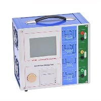
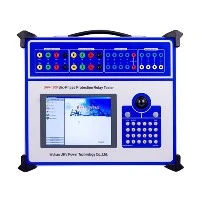
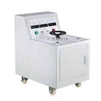
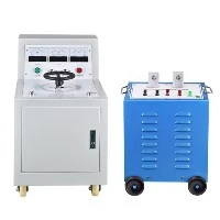
1. Introduction to the complete set of equipment for frequency conversion series resonance test.
The variable frequency series resonance test utilizes the inductance of a reactor and the capacitance of the tested object to achieve capacitance resonance and obtain high voltage and high current. It is a new method and trend in current high-voltage testing, which has been widely used both domestically and internationally. Series resonance is a resonant current filtering circuit that can improve the distortion of power waveform, obtain better sine voltage waveform, and effectively prevent harmonic peak breakdown of the tested object; When the insulation of the test object is punctured, the current immediately becomes detuned, and the loop current rapidly drops to one tenth of the normal test current; When flashover breakdown occurs, due to the loss of resonance conditions, the arc can be extinguished. In addition to the instantaneous reduction of short-circuit current, the high voltage also disappears immediately, and it takes longer to restore voltage. It is easy to cut off the power again under flashover voltage. Therefore, it is suitable for insulation withstand voltage testing of high-voltage and high-capacity power equipment.

2. Application of the complete set of frequency conversion series resonance test equipment in GlS system
The on-site voltage withstand test of GIS is conducted through AC voltage, oscillating lightning impulse voltage, oscillating working pulse voltage, etc. AC voltage withstand test is a commonly used method in the on-site voltage withstand test of GIS, which can effectively check abnormal electric field structures (such as electrode damage). At present, due to limitations in testing equipment and conditions, only on-site voltage testing is conducted. However, most GIS systems that have not undergone on-site AC voltage withstand testing have experienced accidents. Therefore, it is necessary to conduct on-site voltage withstand testing on GIS systems. Currently, due to limitations in testing equipment and conditions, only on-site voltage testing is conducted
(1) Testing requirements
① GlS should be fully installed. SF6 gas should be filled into the rated density, and the resistance measurement of the main circuit, testing of various components, and detection of SF6 gas water content and leakage have been completed. All secondary windings of current transformers have been grounded, and the secondary voltage windings of voltage transformers have been disconnected and grounded. ② Before conducting the AC withstand voltage test, the following equipment should be isolated from the GlS high-voltage wires and busbars. ③ Each newly installed part of GIS must undergo insulation testing. When testing the extended parts, the original parts of adjacent devices should be cut off and grounded.
(2) Method of applying test voltage
Apply the test voltage to the section between the phase conductor and the casing; For other non test phase and shell grounding connections, please apply voltage from the bushing. During the test, apply the voltage to each component of the GlS at least once. At the same time, to avoid insulation aging of the same component, the test voltage should be applied to multiple components. Normally, only perform the phase to ground AC withstand voltage test on site. If the isolation switch of the circuit breaker is damaged or disassembled during transportation and installation, it is necessary to conduct AC dielectric testing on the port. The withstand voltage value should be consistent with the phase to ground AC withstand voltage value. If the total capacitance of the GlS is large, the withstand voltage test can be conducted in sections.
3. AC dielectric testing program
The first stage of AC dielectric testing in GIS is "complex purification", aimed at removing conductive or non-conductive particles that may be present in GIS. These particles may be brought in during installation, or produce metal debris after multiple operations, or form fastener cutting debris and electrode surface burrs. "Precision purification" can move conductive particles to low electric field areas or capture particles, and burn the burrs on the electrode surface without damaging the insulation. The "empirical purification" voltage value should be lower than this voltage value. The second stage is dielectric testing, which is conducted after the "precision purification" process. The time is 1 minute.
4. Judgment of Field Voltage Test Results
If each component of GIS has withstood the specified test voltage according to the selected test procedure without breakdown discharge, it is considered that the entire GIS has passed the test; If breakdown discharge occurs during the testing process, a comprehensive voltage withstand test should be conducted based on the discharge energy, various acoustic, optical, electrochemical, and other discharge effects caused by the discharge, as well as the test results provided by other fault diagnosis techniques during the testing process. If there are no issues, the following steps can be taken:
① Apply the specified voltage and repeat the test. If the equipment or gas barrier can withstand it, the discharge is a self-healing discharge; If the repeated testing voltage reaches a fixed value and the specified time, the tested product is considered qualified, otherwise the following items will be executed. ② Dismantle the equipment, open the exhaust gap, carefully inspect the insulation condition, and take necessary recovery measures before proceeding to the next required voltage test.
5. Methods for locating breakdown faults in GIS voltage withstand tests
If the interval between the incoming and outgoing lines of the voltage withstand test after GIS segmentation is larger, and non self recovery discharge or breakdown occurs during the testing process, it is difficult to determine the exact location of the fault with human ears and only monitor it, which can easily lead to misjudgment and waste of manpower, material resources, and unnecessary equipment damage; If a fault locator is developed based on the principle of shell vibration caused by the shock wave generated by discharge, the discharge interval can be determined. Before each withstand voltage test, sensors can be installed on the testing part, especially on the circuit breaker, isolation switch, busbar, and insulator connection shell of each isolator connection part.