


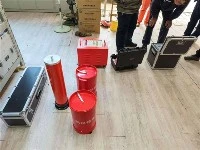

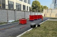
The variable frequency series resonance withstand voltage test is to use the inductance of the reactor and the capacitance of the tested object to form an LC series circuit, adjust the voltage frequency output of the variable frequency power supply, and achieve series resonance.
According to the principle of resonance, when the inductive reactance value X1 of the L reactor is equal to the capacitive reactance value XC in the circuit, the circuit will reach resonance state. At this time, only the circuit resistance R consumes the active power in the circuit, while the reactive power is in the capacitance of the reactor and the test sample, thus generating high voltage on the test sample.
The condition for generating series resonance: XL=XC
Due to the high voltage generated by series resonance in L and C, it may cause damage to the breakdown of coils or capacitors. Therefore, in power engineering, series resonance should be avoided as much as possible, and it is particularly important to use a complete set of variable frequency series resonance test equipment to detect the power system.

Under impedance conditions, the sign of the imaginary part being equal after resonance is opposite. The series impedance is equal to 0, and the parallel impedance is equal to infinity. When resonance occurs, the resonant current of the series circuit is infinite; The resonant voltage of a parallel circuit is infinite (theoretical value). In a series circuit of resistance and inductance, the phenomenon of power supply, voltage, and current in the same phase is called series resonance, which is characterized by pure resistance, power supply, voltage, and current in the same phase. The reactance X is equal to 0, and the impedance Z is equal to the resistance R. At this time, the impedance of the circuit is the smallest, the current is the largest, and the inductance and capacitance may generate voltages many times higher than the power supply voltage. Therefore, series resonance is also known as voltage resonance. Parallel resonance: In a resistor capacitor inductor parallel circuit, the circuit voltage and total current are in phase, which is called parallel resonance. Its characteristics are: parallel resonance is a complete compensation, the power supply does not need to provide reactive power, only provides active power required by the resistor. When resonance occurs, the total current of the circuit is minimized, and the branch current is usually greater than the total current of the circuit, so parallel resonance is also known as current resonance.
In a series circuit of resistors, capacitors, and inductors, directly subtract the influence of inductors XL and XC; If certain conditions are met, simply taking XL=Xc, the reactance of the circuit is equal to zero, the current and voltage phases in the circuit are the same, and reactive power is not exchanged between resistors, inductors, and capacitors. This state of the circuit is called series resonance.
In an AC circuit with resistor R, inductor L, and capacitor C, the voltage across the circuit is usually different from the current phase. If we adjust the parameters or power frequency of circuit components (L or C), they can be in the same phase, and the entire circuit is purely resistive. When the circuit reaches this state, it is called resonance.
In a series circuit composed of resistors, inductors, and capacitors, when capacitor XC=inductor XL is equal, series resonance occurs, and the phase of voltage U and current I in the circuit is the same; When a series resonance occurs in the circuit, the impedance Z=R2+XC-XL2=R, the total impedance of the circuit is minimized, and the current will reach its maximum value.
In a sinusoidal AC circuit with R, L, and C components, the voltage and current at both ends of the circuit are usually different; If the parameter values of circuit components are changed or the frequency of the power supply is adjusted, the voltage and current of the circuit will be in phase, and the impedance of the circuit will display the properties of resistance. This type of circuit is called resonance. According to the different connection forms of the circuit, resonance phenomena can be divided into series resonance and parallel resonance. In the R, l, C series circuit, when XL=XC, the impedance angle ∧=0, that is, the power supply voltage and current are in phase. This phenomenon is called series resonance. The characteristics of series resonance are that when resonance occurs, due to the inductance XL being equal to XC, the impedance reaches its minimum and the circuit resistance is minimized.
When the voltage U is constant, the current I in the circuit reaches its maximum value. Due to the resonance XL=XC, the phase of UL=UC is opposite to UL and UC, so the voltage on the resistor is equal to the power supply voltage. Series circuit resonance has some characteristics. Understanding the resonance phenomenon can utilize these characteristics to prevent the harm caused by certain characteristics. Harmonic filtering devices use the characteristics of series resonance to consider the main harmonic. General reactive power compensation devices should avoid series resonance because when series resonance occurs, the voltage on the capacitor components will rise, which may cause breakdown of the capacitor insulation layer. However, in radio engineering, the signals that need to be received can be extracted using the selectivity of series resonance phenomenon and the obtained high voltage. The quality factor Q of LC frequency selective resonant circuit is defined as: Qo=wo L/R, wo is the resonant frequency of the circuit, and R is the inductance loss resistance L.