

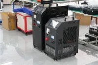


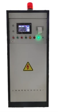
Partial discharge is an "early signal" of insulation degradation in high-voltage electrical equipment, but the signal it generates is extremely weak and has a wide frequency band - extending from several kilohertz to several gigahertz. If the frequency range is not selected correctly, either the true discharge signal will be missed, or the on-site communication interference and frequency converter noise will be reported as partial discharge. The technical team of Wuhan UHV Power Technology Co., Ltd. pointed out that the selection of frequency range is essentially a balance point between "sensitivity" and "anti-interference ability", and this balance point depends on the type of tested equipment and the on-site electromagnetic environment.

Five mainstream frequency bands, each with its own "battlefield"
At present, the mainstream partial discharge detection frequency bands in the industry are roughly divided into five categories, each with clear applicable boundaries.
The low frequency range (10kHz~1MHz) is the traditional pulse current method. This method is endorsed by standards such as IEC 60270 and GB/T 7354-2018. It directly measures the charge of discharge pulses through coupling capacitors and can provide quantitative results in picoku (pC) units.
The high-frequency current method (HFCT, 3MHz~30MHz) raises the frequency window by an order of magnitude. The sensor is clamped on the grounding wire or cable shielding layer of the device, coupled with the high-frequency current induced by the discharge pulse in the grounding circuit. This frequency band avoids power frequency noise and most low-frequency interference, while the energy of discharge pulses is still considerable within this range. According to industry technical data, the signal attenuation of the high-frequency current method in cross-linked polyethylene cables is only 0.5dB/100m, which can support the detection of long-distance cable segments. HFCT is the main method for live inspection and online monitoring of equipment such as cables, transformers, and reactors.
The transient earth voltage method (TEV, 3MHz-80MHz) is designed for metal enclosed equipment. When discharge occurs inside the switchgear, rapid current pulses will cause transient potential changes at the seams, flanges, and grounding connections of the cabinet. TEV sensors can capture this signal on the surface of the cabinet. Its characteristics are no need for electrical connections, simple operation, and suitable for rapid inspection of switchgear. However, the TEV signal strength is greatly affected by the cabinet structure and sensor coupling status, and it is not appropriate to directly compare the readings on different cabinets horizontally.
The ultra-high frequency method (UHF, 300MHz~3GHz) is currently the most robust anti-interference solution. The rise time of the discharge pulse is extremely short, and the corresponding spectral energy is still concentrated in the ultra-high frequency band. The UHF frequency band is far away from power frequency, radio broadcasting, and most industrial noise, with extremely high signal-to-noise ratio, and can capture extremely weak discharge signals. GIS equipment is the main battlefield of UHF - the coaxial metal cavity itself is a natural electromagnetic waveguide, where UHF signals propagate with minimal attenuation, and the casing can also shield external interference. The internal discharge detection of oil immersed transformers is also applicable to UHF. However, it should be noted that UHF provides mostly relative amplitudes, and to obtain quantitative results at the pC level, calibration still needs to be carried out in conjunction with the standard pulse current method.
The ultrasonic method (AE, 20kHz~300kHz) takes another path - measuring sound waves instead of electrical signals. The mechanical vibration waves generated by discharge are received by piezoelectric sensors on the surface of the equipment and are completely unaffected by electromagnetic interference. Surface discharge positioning of switchgear and GIS, investigation of abnormal sound sources in transformer bushings, and ultrasonic waves are all effective tools. Its weakness is that the signal propagation attenuation inside the device is relatively large, and its sensitivity to deep internal discharge is not as good as UHF.
The first step in selection: first look at the equipment, then look at the environment
Once the technical characteristics of each frequency band are determined, the logic of selection becomes clear. Wuhan UHV technicians repeatedly emphasize a principle when analyzing partial discharge detection systems: the frequency response range must match the signal characteristics of the tested equipment, and the error caused by frequency mismatch is often more serious than the accuracy problem of the instrument itself.
At the practical level, UHF is the preferred method for internal discharge detection of GIS and metal enclosed switchgear, combined with ultrasonic positioning verification; The insulation state evaluation of cables and transformer windings, and the high-frequency current signal of HFCT can best reflect the discharge characteristics in the grounding circuit; The combination of TEV and ultrasonic waves is the most efficient for daily inspection of switchgear. Both are non-invasive inspections that do not require power outages or equipment disassembly. If the goal is to obtain a quantitative pC value that complies with the IEC 60270 standard, such as factory testing or type testing, then it is necessary to return to the standard pulse current method in the low-frequency range.
The on-site electromagnetic environment is another decisive factor. In places with dense interference sources such as substations and industrial plants, low-frequency instruments are easily overwhelmed by signals from frequency converters, rectifiers, and communication base stations.
Adjustable frequency range: an underestimated selection indicator
It is worth noting that the measurement frequency of some partial discharge testers is not a fixed value, but can be adjusted within a certain range. This adjustable design has great value in practical use - when there is severe on-site interference, the passband can be tightened, sacrificing some signal energy in exchange for a higher signal-to-noise ratio; In laboratory environments with minimal interference, wide bandwidth can be used to obtain more complete discharge pulse waveforms.
When selecting, if you only look at the general parameter of "frequency range 10kHz~1MHz", it is easy to overlook the on-site adaptability brought by frequency adjustability. For operation and maintenance units that need to switch between multiple environments, adjustable frequency range is more practical than "wideband" itself.
The frequency range is the first threshold for selecting a partial discharge tester and also the easiest place to step on. Skipping this step to compare sensitivity, channel count, or analysis functionality often results in buying a device with beautiful parameters but not actually usable. First, determine which frequency band the tested device is "speaking" in, and then choose an instrument that can understand that frequency band. The direction of selection will not be wrong.