

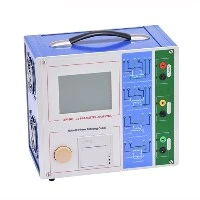
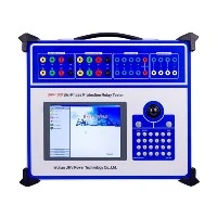
TTR stands for Transformer Turns Ratio Tester.
As the name suggests, it is a specialized portable electronic test instrument designed to measure the turns ratio and related parameters of power transformers or other electromagnetic devices (such as voltage transformers).

Here's a detailed explanation of the TTR Tester:
1.Core Function: Measuring Turns Ratio
The turns ratio of a transformer is the ratio of the number of turns in its high-voltage winding to the number of turns in its low-voltage winding. It determines the transformer's voltage transformation capability (e.g., a 1000:1 ratio means that applying 1000V on the HV side should theoretically output 1V on the LV side).
The TTR tester applies a low-voltage, low-current AC test signal to one winding of the transformer (usually the HV side) and precisely measures the voltages across both windings, automatically calculating the actual turns ratio.
It compares the measured actual ratio to the transformer's rated ratio (nameplate or design value) and calculates the ratio error (percentage deviation). This error is a critical indicator of winding health.
2.Key Roles and Significance:
Verification of Manufacture/Design: Confirms the winding turns ratio meets design specifications after manufacturing or major repair.
Detecting Winding Faults: This is one of the most important uses of TTR testing. It effectively detects:
Inter-Turn Shorts: Short circuits between a few turns within a winding change the effective turns ratio, causing a deviation from the rated ratio.
Open Windings: No ratio can be measured.
Tap Changer Problems: Verifies the correct ratio at each tap position and checks for poor contact (which causes ratio abnormalities).
Winding Deformation/Displacement: Severe winding distortion can also affect the ratio.
Confirming Vector Group (Phase Relationship): Many advanced TTR testers measure not only the ratio magnitude but also the phase angle difference between the HV and LV voltage signals. This determines the transformer's vector group (e.g., Dyn11, Yyn0), ensuring correct phase relationships for parallel operation or system connection.
Excitation Current Measurement: Some TTR testers can simultaneously measure the excitation current flowing into the winding when the test voltage is applied. Abnormal excitation current may indicate core problems (e.g., inter-laminar shorts, magnetic circuit faults) or severe winding issues.
Polarity Verification: Determines the relative polarity (additive or subtractive) of the transformer windings.
3.Simplified Working Principle:
The instrument internally generates a precise, low-voltage (typically a few volts to tens of volts), low-frequency (usually power frequency or close, e.g., 50/60 Hz) AC test signal.
This voltage is applied to one winding of the transformer under test (e.g., HV side H1-H2).
The instrument's high-precision voltmeters simultaneously measure the voltage (V1) on the energized winding and the induced voltage (V2) on the other winding (e.g., LV side X1-X2).
The instrument's microprocessor calculates the actual turns ratio (TR = V1/V2).
It compares this to the user-entered rated ratio, calculating the percentage error.
(For instruments with phase measurement capability) Measures the phase difference angle between V1 and V2.
Displays or stores the results (ratio, error %, phase angle, excitation current, etc.).