

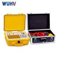


### **1. What is a CT/PT Tester?**
A **CT/PT Tester** is a specialized electrical test instrument designed to perform diagnostic tests on **Current Transformers (CTs)** and **Potential (Voltage) Transformers (PTs)**. These devices verify the accuracy, insulation integrity, and overall condition of CTs and PTs used in power systems for measurement, protection, and metering.
---
### **2. Purpose**
* **Verify accuracy and ratio:** Check turns ratio and burden of CTs and PTs to ensure correct scaling of current and voltage signals.
* **Detect insulation faults:** Measure insulation resistance and withstand voltage to detect deterioration.
* **Evaluate excitation characteristics:** Measure excitation current and magnetizing inductance of CTs to assess core condition.
* **Quality assurance:** Ensure new CTs/PTs meet design specifications.
* **Routine maintenance:** Identify early faults to avoid equipment failure and misoperation of protection relays.
---
### **3. Types of CT/PT Testers**
* **Ratio & Polarity Testers:** Measure CT/PT turns ratio, phase angle, and polarity.
* **Excitation Current Testers:** Measure the excitation curve of CT cores, indicating magnetic health.
* **Insulation Testers:** Megohmmeters and hipot testers for dielectric integrity.
* **Combined Multifunction Testers:** Integrated devices that perform ratio, excitation, insulation, and resistance tests.
* **Portable Field Testers:** Battery-powered units for on-site testing with rugged design.
---
### **4. Applications**
* **Substations & Power Plants:** Routine and commissioning tests of CTs and PTs used for protection and metering.
* **Manufacturing:** Acceptance testing during production.
* **Maintenance Facilities:** Troubleshooting and condition monitoring.
* **Utility Service Checks:** Field verification to prevent relay misoperation and billing errors.
* **Research & Development:** Testing new CT/PT designs.
---
### **5. How to Use a CT/PT Tester**
1. **Preparation**
* De-energize and isolate the CT/PT.
* Verify wiring diagrams and test point access.
* Ensure safety precautions and proper grounding.
2. **Connection**
* Connect test leads to CT primary and secondary terminals (or PT high and low voltage terminals).
* Connect auxiliary leads as needed for insulation or excitation tests.
3. **Select Test Mode**
* Choose the desired test: ratio, polarity, excitation, insulation resistance, or hipot.
4. **Configure Test Parameters**
* Enter rated CT/PT parameters such as rated current, voltage, and burden if required.
5. **Perform the Test**
* Initiate the test and monitor readings.
* For excitation tests, plot the excitation curve if supported.
6. **Analyze Results**
* Compare results against manufacturer specifications or standards.
* Identify abnormalities such as ratio errors, high excitation current, or insulation breakdown.
7. **Document**
* Save or print test results and generate reports.
---
### **6. FAQs**
**Q1: Why is CT ratio testing important?**
**A:** Accurate CT ratio ensures correct current measurement for metering and reliable relay operation. Incorrect ratios can cause protection failures or billing errors.
---
**Q2: What does the excitation current test reveal?**
**A:** It indicates the CT core's magnetic condition. Abnormally high excitation current can signify core saturation, damage, or aging.
---
**Q3: How is PT testing different from CT testing?**
**A:** PT testing focuses more on voltage ratio, insulation resistance, and polarity, while CT testing also includes excitation current and burden checks.
---
**Q4: Can these testers be used on energized CTs/PTs?**
**A:** No, tests must be performed on de-energized equipment for safety and accuracy.
---
**Q5: What standards govern CT/PT testing?**
**A:**
* IEC 60044 (CTs) and IEC 60044-2 (PTs)
* IEEE C57.13 (Instrument Transformers)
* ANSI standards C57.13, C57.16
---
**Q6: How often should CTs and PTs be tested?**
**A:** Typically during commissioning, after repairs, and periodically every 3-5 years or per utility maintenance schedules.
---
**Q7: What are common signs of CT/PT failure?**
**A:** Ratio errors, polarity reversal, increased excitation current, insulation failure, or physical damage.
---
**Q8: What safety precautions are needed?**
**A:** Ensure CT secondary circuits are never open while energized, isolate equipment, use PPE, and follow lockout/tagout procedures.