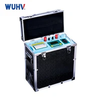

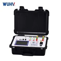


Portable Transformer Short-Circuit Impedance & Load Loss Tester
The Transformer Short-Circuit Impedance & Loss Tester measures voltage, current, and power under specified short-circuit test conditions and automatically calculates key transformer parameters. The measured results can be compared directly with transformer nameplate data, factory test records, or historical field measurements, providing engineers with a reliable method to evaluate transformer condition and detect internal mechanical changes.
Key Testing Capabilities
Short-Circuit Impedance Measurement
The tester measures the electrical parameters required to determine transformer short-circuit impedance under specified test conditions.
Impedance Voltage Measurement
Impedance voltage indicates the voltage required to produce the specified test current when designated transformer windings are short-circuited. Measured values are evaluated against rated reference data during acceptance testing and quality verification.
Load Loss Measurement
Evaluates total active power loss under short-circuit test conditions. Load-loss measurements are essential during transformer manufacturing, factory acceptance testing (FAT), and routine performance checks to ensure compliance with guaranteed efficiency values.
Integrated Voltage, Current, and Power Measurement
By integrating multi-parameter measurement into a single device, this tester eliminates the need for separate voltage, current, and power meters-significantly reducing manual calculations and connection errors during routine field testing.
Main Benefits for Transformer Testing
Baseline-Driven Condition Assessment: Quickly compare real-time data with factory records or commissioning baselines to track transformer health over time.
Combined Impedance & Loss Measurement: Perform complete short-circuit impedance and load loss evaluations in a single test setup, reducing labor time and equipment clutter.
Versatile Field & Factory Application: Compact, rugged design built for transformer manufacturing plants, high-voltage test laboratories, and demanding field environments.
Digital Test Record Management: Built-in digital storage and data export capabilities allow utilities and testing contractors to easily generate standard inspection reports and preserve historical data.
Typical Applications
Transformer Manufacturing & FAT
Manufacturers and independent inspectors can verify specified parameters against design requirements and standards before product release.
Transformer Commissioning
Establishes an essential on-site baseline after transit and installation, ensuring the unit arrives undamaged before initial energization.
Preventive Maintenance & Asset Management
Integrate impedance testing into periodic maintenance workflows to detect subtle winding deterioration before catastrophic failure occurs.
Post-Fault Inspection
Provides immediate electrical evidence regarding winding integrity after an external fault trip, aiding in informed re-energization decisions.
Typical Short-Circuit Impedance Testing Workflow
Verify Baseline Data
Review transformer nameplate, rated capacity, vector group, and test requirements.
Prepare Connection
Short-circuit the designated secondary/tertiary winding according to standard procedures.
Hook Up Instrument
Connect voltage and current measurement leads to the designated winding.
Safety Verification
Confirm ground connections, interlocks, and test zone safety before energizing.
Apply Test Voltage
Inject specified test voltage/current into the test circuit.
Data Capture
Record voltage, current, power, and frequency simultaneously.
Automated Calculation
The tester computes short-circuit impedance, impedance voltage, and corrected load loss.
Result Evaluation
Compare results against factory acceptance criteria or historical reference points.
Export & Report
Save the dataset and export standard test reports for quality documentation.
Supported Transformer Types
This testing system supports a wide range of transformer designs across industrial and utility applications:
Power Transformers (GSU, Transmission)
Distribution Transformers
Single-Phase & Three-Phase Units
Oil-Immersed & Dry-Type Transformers
Technical Specifications
|
Specification |
Technical Parameter |
|
Impedance Range |
[Actual Value] |
|
Impedance Voltage Range |
[Actual Value] |
|
Load Loss Range |
[Actual Value] |
|
Voltage Measurement Accuracy |
[Actual Value] |
|
Current Measurement Accuracy |
[Actual Value] |
|
Power Measurement Accuracy |
[Actual Value] |
|
Test Frequency Range |
45 Hz – 65 Hz / [Actual Value] |
|
Data Storage / Export |
USB / RS232 / Custom Software |
|
Power Supply |
AC 220V ±10%, 50Hz/60Hz / [Actual Value] |
|
Operating Temperature |
-10°C to +50°C |
|
Applicable Standards |
IEC 60076, IEEE C57.12.90 |
Technical Documentation Available for Buyers
To support procurement evaluations, technical audits, and tender approvals, buyers can request the following document package:
- Product Datasheet & Full Specifications
- User Operation Manual & Wiring Diagrams
- Factory Calibration Certificate / ISO Calibration Report
- Sample Diagnostic Test Report
- Accessory & Test Lead Selection Guide
FAQ
Q: What is a transformer short-circuit impedance test?
A: A transformer short-circuit impedance test measures the electrical parameters of a transformer when one winding is short-circuited and the specified test voltage is applied to another winding.
Q: Why is transformer short-circuit impedance important?
A: Short-circuit impedance is an important transformer characteristic. Comparing measured impedance with factory or historical reference data can help engineers identify significant changes that may require further investigation.
Q: Can short-circuit impedance testing identify winding deformation?
A: A significant change in short-circuit impedance may indicate a possible change in winding mechanical condition.
Q: When should transformer short-circuit impedance testing be performed?
A: Common applications include factory testing, factory acceptance testing, commissioning, preventive maintenance, transformer overhaul and inspection following a significant external short-circuit event.
Q: What is the difference between short-circuit impedance and load loss?
A: Short-circuit impedance describes the impedance characteristics of the transformer under the specified short-circuit test condition. Load loss represents the power loss measured under the specified load test condition.
Q: Can this tester be used for three-phase transformers?
A: A tester configured for three-phase testing can be used with applicable three-phase transformer connections. The correct test method depends on the transformer winding configuration and the functions and ratings of the selected instrument.
Q: Why should impedance test results be compared with previous measurements?
A: A historical measurement provides a baseline for comparison. Factory, commissioning and maintenance records can help engineers determine whether the current impedance has changed significantly over time.
Q: What information should I provide when selecting a transformer impedance and loss tester?
A: Provide the transformer rated capacity, voltage level, single-phase or three-phase configuration, winding connection, required test parameters, expected test voltage and current, testing environment and applicable standards.
Hot Tags: transformer short-circuit impedance & loss test, China transformer short-circuit impedance & loss test manufacturers, suppliers, factory, High Current Battery Discharge Test Set