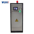
Impluse Voltage Generator

Impluse Voltage Generator
An impulse generator is an electrical equipment which can imitate lightning stricks and switching surges. and produces very short high-voltage or high-current surges. The system usually can produce standard full lightning impulse wave and chopped lightning impulse wave and usually be used to test the strength of electric power equipment against lightning and switching surges. its waveform parameters fully complying with IEC, GB and other domestic and international standards.


Features of Lightning Impluse Test System
(1) The main equipment consists of 2~ 6~ arbitrary sections, forming a combined tower structure. Each level is stacked step by step, making disassembly and inspection convenient, and the overall structure is stable;
(2) The body adopts a bilateral symmetrical charging method, with controllable silicon constant current voltage regulation, continuously adjustable from zero to the set voltage, and the charging power supply automatically shuts off at the moment of ignition and discharge. The rectifier silicon stack device is assembled on the impact body to form a charging and rectification integrated device, with a rated voltage of 200kV per stage;
(3) The insulation pillar of the main body is a 6-stage tower structure Each level includes 2 MWF100-1.0 iron shell oil immersed pulse capacitors, which are hung on the outside of steel brackets and connected to each other with epoxy glass cloth plates to form a complete component. Four epoxy pipes are used to support the components, with a total of 6 levels, stacked into a high-pressure tower. Charging resistor, wave head resistor, wave tail resistor, and ignition ball gap, etc. When lightning waves are generated, short-circuit the operating wave head resistor with a short-circuit rod,
Choose appropriate lightning wave head resistance, tail resistance, and stage number; When the capacitance of the test sample is greater than 3000pF and less than 10000pF, remove the short-circuit rod and operate the external wave head resistor to place a suitable capacity modulation resistor into the circuit. When an operational impulse voltage wave is generated, remove the short-circuit rod, connect the external wave head resistor of the operational wave to the discharge circuit, remove the tail resistors of each level of lightning wave, and connect the tail resistors of the operational wave to the discharge circuit.
(4) Single pulse capacitor 10.05F, DC working voltage 100kV, capacitor inductance 0.2H, composite film oil immersed insulation. Under normal working conditions and working environment, the capacitor output bushing can withstand a vertical tension of 15kg while ensuring no damage or oil leakage;
(5) The front and tail resistors of the wave adopt a plate-shaped structure, with no inductive winding, and have a self inductance of 2.5H (the purpose of reducing inductance is to increase the load capacity. For ultra large capacity loads (such as those greater than 5000PF), a suitable combination of external wave capacitors and wave resistors can be used to increase the load), The joints are all spring-loaded;
(6) The wave head (front) and wave tail resistor bracket can be composed of four resistors connected in parallel at the same time. The length of the wave head (front) and wave tail resistors is equal and can be used interchangeably. Each stage is equipped with a location to store excess wave adjusting resistors and short-circuit rods; Inserting a short-circuit rod can facilitate the series operation of the generator;
(7) The complete set is equipped with 3 sets of lightning wave head resistors and 2 sets of wave tail resistors; (including one set of gap resistors)
(8) The first level ball gap is triggered by double-sided opposite polarity, and the second to ninth level ball gaps are all ignited by three gap ball gaps, with a synchronous misoperation rate or refusal rate of no more than 2%; The synchronization range is ≥ 20%.
(9) The distance between each level of ball gap is adjusted linearly by an electric motor, and the control system indicates the charging voltage corresponding to the ball distance. The transmission structure is equipped with upper and lower limit switches;
(10) The ball gap distance can be manually or automatically adjusted on the control system;
(11) The body can be used in parallel every two or more levels, and the parallel connecting rod adopts a unified connector for easy replacement. The device can accommodate excess wave modulation resistors without affecting electrical performance;
(12) The main body is equipped with an insulation ladder, and there is an insulation platform every three levels. Its load capacity is designed to be 120kg to facilitate the replacement of wave adjusting components by staff. Each level is tested and stored with a bracket for wave adjusting resistors and connecting rods;
(13) The bottom level of the body adopts solid insulation columns, while other levels use two end sealed insulation cylinders with good sealing performance;
(14) Anti corona measures are taken at all levels, and there will be no significant corona during the entire charging process.
(15) Equipped with a safety grounding system, it is convenient for test personnel to start the grounding system when climbing the body to replace resistors or for maintenance. All capacitors should be short circuited and grounded.
(16) Equipped with an automatic grounding system, when charging is stopped or an emergency button is pressed, the automatic grounding system starts, and the main capacitor of the generator is automatically grounded through a discharge resistor;
(17) The inter level insulation and mechanical support can withstand 220kV DC voltage without discharge.
(18) The climbing insulation ladder installed on the body is convenient to work and safe and reliable. The mechanical strength of the body can fully meet the mechanical and electrical requirements.
(19) The top of the generator is equipped with a pressure equalizing cover, which is composed of stainless steel tube rings with a diameter of 19 welded together.


Parameters of Lightning Impluse Test System
| Nominal lightning impulse voltage | ±1200 kV |
| Rated stage voltage | ±200 kV |
| Rated charging voltage | ±100 kV |
| Nominal capacitance (energy) | 60 kJ |
| Total impulse capacitance | 0.0833 μF (single pulse capacitor: 1.0 μF / 100 kV, 18 pcs in total) |
| Pole number | 6 pcs |
| Single section electrical capacity | 1.0 μF |
| Single section energy | 10 kJ |
Impulse voltage waveform parameters
When the load capacitance is below 300-4000PF, it can generate:
| Standard lightning impulse full wave | 1.2 ± 30% μs / 50 ± 20% μs |
| Amplitude tolerance | ±3% |
| Peak oscillation | ≤ 5% of the amplitude |
| Chopping time | 2–6 μs, delay controllable |
| Efficiency | ≥ 90% |
| Chopped-wave generation capability | By using a chopping device, lightning impulse waves with a chopping time of 2–6 μs can be generated |
| Chopped-wave dispersion | < 100 ns |
These two types of impulse voltage waveform parameters and their deviations comply with the requirements of relevant national GB311 and GB16927 standards.
| Minimum output voltage | > 10% Un |
| Synchronization range | The voltage level is within the range of 20% to 100% of the rated voltage, and the positive and negative polarity synchronization range ≥ 20%. |
| Out-of-control rate of synchronous discharge | < 2% |
| Body inductance | ≤ 55 μH |
| Ignition range | 10%–100% Un |
| Charging voltage instability | < ±1.0% |
| Deviation between charging voltage and reference voltage | < ±1.0% |
| Voltage utilization factor |
• When the load capacitance is below 1000 pF, the voltage utilization factor of standard lightning wave is ≥ 90%, and the voltage utilization factor of standard operating impulse voltage full wave is ≥ 85%. • When the load capacitance is below 3000 pF, the voltage utilization coefficient of standard lightning wave is ≥ 85%, and the voltage utilization coefficient of standard operating impulse voltage full wave is ≥ 75%. |
| Duration | Continuous operation can be achieved by charging and discharging every 120 seconds above 70% rated voltage, and continuous operation can be achieved below 70% rated voltage. |
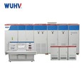
Equipment List
|
Item |
QTY |
|
Impulse voltage generator body (including all waveform modulation components) |
1 set |
|
DC charging device |
1 set |
|
Weak damping capacitor voltage divider |
1 set |
|
Multi ball cutt off device |
1 set |
|
Computer-controlled measurement system |
1 set |
|
Accessories (Secondary circuit measurement wire, control line, wave head resistance, wave tail resistance, grounding rod, grounding copper foil etc) |
1 set |
Advantages of Wuhan UHV Power Technology’s Lightning Impluse Test System
1.Precise Waveform Control: Self-developed fully digital control platform and waveform shaping circuit deliver standard full/cutoff lightning waves (1.2/50μs, 1.2/2~5μs) with distortion ≤2%, far better than the national standard ≤5%.
2. Strong Anti-interference: Designed for harsh EM environments (substations, chemical plants); fiber isolation + shielding ensure stable, repeatable waveforms under complex conditions.
3. High-precision Closed-loop Control: Charging voltage feedback accuracy 0.5% + 1GS/s high-speed sampling captures microsecond-level waveform details for accurate, reliable data.
4.Ultra-compact Modular Design: 4-stage fully insulated capacitor structure reduces size by ~40% vs. traditional systems; ideal for space-constrained sites (mountains, offshore wind, compact substations).
5.Wide Voltage Coverage: Customizable voltage levels from MV to UHV; one system fits multiple voltage-class DUTs (transformers, GIS, cables, insulators, etc.).
6.Strong Load Capacity: Maintains standard waveforms without obvious distortion even for large capacitive/inductive loads.
7.Full-process Automation: One-click operation auto-completes charging, triggering, discharging, acquisition, analysis, storage; 70% less manual work.
8.Intelligent Analysis & Reporting: Auto-calculates waveform parameters, compares with standards, generates IEC/GB-compliant reports; supports data export and waveform replay.
9.Multi-mode Operation: Manual / auto / programmable modes available; easy for new users, efficient for experts.
10.Comprehensive Safety Protection: HV interlock, door interlock, emergency stop, overvoltage/overcurrent protection, automatic residual voltage discharge; full discharge after test eliminates electric shock hazards.
11.Fiber-isolated Control: Fiber communication between console and HV mainbody provides complete electrical isolation to protect operators.
12. Reliable Insulation: Key components use epoxy/porcelain insulation with sufficient creepage distance for long-term safe operation.
13.Direct from Manufacturer, Cost-effective: High-tech enterprise in Wuhan Optics Valley; R&D and production in-house, no middlemen, better value for same specs.
14.Authoritative Certifications: ISO, CNAS, CE; 20+ patents; proven in State Grid & major projects (e.g., Zhoushan 500kV submarine cable).
15.Nationwide Rapid Service: 2-hour response, 48-hour on-site arrival; 24/7 technical support, on-site commissioning + training + after-sales.
16.Nearly 20 Years of Expertise: Specialized in HV testing with 98% customer repeat rate and strong industry reputation.
17.Optimized for Harsh Environments: Adapted to high humidity, dust, strong interference, flammable/explosive conditions; designed for chemical plants, power plants, substations.
18.Customized Solutions: Voltage, waveforms, interfaces, software can be tailored to DUT, site, standards (GB/IEC/ANSI).


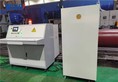
Application Scenarios and Image Examples
Lightning impulse withstand voltage test for transformer

Lightning impulse withstand voltage test for insulator

Lightning impulse withstand voltage test for insulator

FAQS
Q1: What is a lightning impulse test system used for?
A: It simulates natural lightning surge voltage to test the lightning overvoltage withstand capacity of insulation on high-voltage electrical equipment. It can detect hidden insulation defects such as cracks, voids and impurities, and is mandatory for type tests, factory tests and handover tests.
Q2: What are the standard waveforms it can generate?
A: Two mainstream standard waveforms are available: full lightning impulse wave (1.2/50 μs) and chopped lightning impulse wave (1.2/2~5 μs), fully compliant with IEC and GB standards.
Q3: How to confirm the required voltage level for my equipment?
A: Please provide the rated voltage of your test objects and corresponding test specifications. We will recommend the matched voltage grade and stage quantity of the impulse generator.
Q4: Can this system work with large capacitance or inductance test objects?
A: Yes. Our system features strong load adaptability. It can maintain standard waveforms without obvious distortion when testing capacitive or inductive equipment like power cables, transformers and GIS.
Q5: What is the adjustable range of core waveform parameters?
A: Wave front steepness, wave tail duration and output voltage amplitude are continuously adjustable. All parameters can be fine-tuned to meet different test requirements.
Q6: What are the advantages of your modular design?
A: The modular structure is compact and space-saving, about 40% smaller than traditional devices. It is easy to transport, install and maintain, and fits narrow substations, wind farms and other space-limited sites.
Q7: How about the waveform stability and repeatability?
A: Adopting fully digital control and shielding design, the waveform distortion is lower than 2%. Equipped with high-speed sampling unit, test waveforms show excellent consistency even under complex electromagnetic interference.
Q8: Is the system difficult to operate? Do we need professional technicians?
A: It supports one-click automatic operation. The whole process including charging, triggering, discharging and data acquisition can be finished automatically. Operators can master basic use after simple training. Manual mode is also reserved for professional testing.
Q9: Does it support automatic report generation and data export?
A: Yes. The system can automatically calculate waveform parameters, generate IEC/GB standard test reports, and support waveform playback, data export and file archiving.
Q10: What safety protection functions does the system have?
A: It is equipped with complete protection: high-voltage interlock, door safety interlock, emergency stop, overvoltage & overcurrent protection, and automatic residual voltage discharge. The console adopts optical fiber isolation to realize complete electrical isolation.
Q11: Is it safe to use in humid, dusty or industrial environments?
A: Key components adopt high-performance insulating materials with sufficient creepage distance. The whole machine has dustproof and moistureproof design, adapting to power plants, chemical parks and other harsh working conditions.
Q12: Do you have international certifications for export?
A: Our products have passed ISO quality management system, CE and other international certifications, and hold more than 20 technical patents. All documents can be provided for export clearance.
Q13: What is your warranty and after-sales service policy?
A: We provide 1-year free warranty for the whole equipment, plus lifelong technical support. We offer on-site commissioning and operation training. Our service team can arrive at the site within 48 hours nationwide within nigotiated dates worldwide.
Q14: What kinds of equipment can this system test?
A: It is widely used for lightning impulse tests of power transformers, high-voltage cables, GIS/HGIS, insulators, switchgears, surge arresters and motor windings.
As one of the leading impluse voltage generator manufacturers and suppliers in China, we warmly welcome you to buy high-grade impluse voltage generator made in China here from our factory. For price consultation, contact us.
hipot dielectric breakdown test setup, electronics hipot compliance tester, high voltage contact tester