

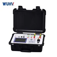


Testing the insulation resistance of a Current Transformer (CT) is important to ensure that the insulation between the primary and secondary windings is in good condition. This test helps identify any insulation breakdown or degradation that could compromise the CT's performance and safety. Here's a general guide on how to test CT insulation resistance:
Tools and Equipment Needed:
Megohmmeter (Insulation Resistance Tester):
A megohmmeter is a specialized instrument designed to measure high resistances, typically in the range of megaohms (MΩ) to teraohms (TΩ).
Test Leads:
Insulated cables with appropriate connectors for making connections to the CT terminals.
Safety Equipment:
Personal protective equipment (PPE) such as gloves and safety glasses.
Steps to Test CT Insulation Resistance:
1. Safety Precautions:
Ensure that all safety precautions are followed, and appropriate PPE is worn.
Verify that the CT and the equipment are de-energized before starting the test.
2. Identification of CT Terminals:
Identify the primary and secondary terminals of the CT. Refer to the CT's documentation or markings on the device to determine the terminal designations.
3. Disconnect the CT:
Disconnect the CT from the power system to isolate it for testing. This is crucial to ensure that the test is performed on the CT itself and not on the entire circuit.
4. Connect the Megohmmeter:
Connect the megohmmeter to the CT terminals using the insulated test leads. Connect the positive lead to the primary side and the negative lead to the secondary side. Follow the polarity as per the CT's markings.
5. Set Test Voltage:
Set the test voltage on the megohmmeter. The test voltage is typically specified by the CT manufacturer and is based on the insulation characteristics of the CT. Common test voltages range from 500 volts to 5,000 volts.
6. Initiate the Test:
Initiate the insulation resistance test using the megohmmeter. The instrument will apply the specified test voltage and measure the resistance between the primary and secondary windings.
7. Record Measurements:
Record the insulation resistance measurements displayed by the megohmmeter. Measurements are typically provided in megaohms (MΩ) or gigohms (GΩ).
8. Interpret Results:
Evaluate the insulation resistance measurements. Higher insulation resistance values indicate better insulation integrity. Compare the measured values with the manufacturer's specifications or industry standards.
9. Documentation:
Document the insulation resistance test results, including the test voltage applied.
Keep records for future reference and compliance with maintenance and safety regulations.
10. Reconnect the CT:
After completing the insulation resistance test, reconnect the CT to the power system if it is part of an active circuit.
Always follow the manufacturer's guidelines and industry standards for insulation resistance testing. If you are unsure or lack experience, it's advisable to seek assistance from qualified professionals. Insulation resistance testing is an essential part of routine maintenance to ensure the reliability and safety of Current Transformers in electrical systems.