



### **1. What is an Impulse Voltage Generator?**
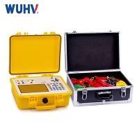
An **Impulse Voltage Generator** is a high-voltage test device that produces short-duration, high-voltage surges (impulses) to simulate overvoltages such as lightning strikes or switching surges in electrical power systems.
These impulses are standardized in **shape** and **duration** to replicate real-world transient stresses on insulation.
---
### **2. Purpose**
* **Simulate overvoltages** (lightning / switching) for testing electrical insulation.
* **Verify dielectric strength** of high-voltage apparatus under transient stress.
* **Ensure compliance** with IEC, IEEE, and national HV test standards.
* **Detect insulation defects** that may not appear under steady-state AC/DC testing.
---
### **3. Applications**
* **Power transformers** (lightning impulse test, switching impulse test)
* **High-voltage cables** (type testing)
* **Gas-insulated switchgear (GIS)**
* **Surge arresters**
* **Bushings & insulators**
* **Generators and large motors**
* **Research labs** for insulation materials and equipment design validation
---
### **4. How to Use**
1. **Setup**
* Place the IVG in a shielded high-voltage test area.
* Connect the test object to the impulse generator's output terminal.
* Ground the test area and personnel safety equipment.
2. **Configure Parameters**
* Select impulse type: *Lightning impulse (1.2/50 µs)* or *Switching impulse (250/2500 µs)*.
* Adjust the number of stages to achieve the required voltage.
* Set polarity (positive/negative).
3. **Charge**
* The generator's capacitors are charged to a pre-set voltage via a DC charging supply.
4. **Trigger Impulse**
* A triggered spark gap or solid-state switch discharges the capacitors in series through a shaping network, creating the required impulse waveform.
5. **Measurement & Verification**
* Measure impulse shape and peak voltage with a high-voltage divider and digital oscilloscope.
* Compare with standard waveforms to verify compliance.
6. **Discharge**
* After testing, ensure all capacitors and the test object are completely discharged to ground.
---
### **5. FAQs**
**Q1: What are the standard impulse waveforms?**
**A:**
* **Lightning Impulse:** 1.2 µs rise time, 50 µs fall time (1.2/50 µs)
* **Switching Impulse:** 250–2500 µs rise/fall times (slower waveform)
* Standards: **IEC 60060-1**, **IEEE Std 4**
---
**Q2: Why not use AC or DC Hipot instead of an impulse test?**
**A:**
AC/DC Hipot applies steady-state stress, which doesn't mimic the fast overvoltages seen in service. Impulse tests reveal **weak points in insulation** that fail under rapid transients but may survive steady voltage.
---
**Q3: How is the output voltage determined?**
**A:**
By the number of stages, stage capacitance, and charging voltage. For example, a 10-stage generator at 100 kV per stage = 1 MV peak.
---
**Q4: What is "stage" in an impulse generator?**
**A:**
A stage consists of a capacitor, a charging resistor, and a discharge/spark gap. Multiple stages are connected in series during discharge to reach high voltage.
---
**Q5: What's the difference between positive and negative impulses?**
**A:**
* **Positive impulses** stress the insulation in one polarity (often more severe for external insulation).
* **Negative impulses** may stress internal insulation more, depending on equipment design.
Standards often require both polarities.
---
**Q6: Can an IVG test partial discharge?**
**A:**
Impulse voltage tests are not typically for PD measurement, but **oscillographic analysis** of the waveform can reveal abnormal distortions due to internal discharges.
---
**Q7: What safety measures are necessary?**
**A:**
* Isolate the test zone with interlocks.
* Use proper grounding and discharge rods after each shot.
* Keep all personnel outside the hazard zone during operation.
---
**Q8: What's the lifetime of an impulse generator?**
**A:**
With proper maintenance (spark gap cleaning, capacitor conditioning, insulation checks), many IVGs operate for **20–30 years** in labs.
---
**Q9: Can the IVG produce oscillating impulses?**
**A:**
Yes - by modifying the shaping circuit, oscillating waveforms can be generated for special insulation studies.
---
**Q10: What are the limitations?**
**A:**
* Large size and weight for MV–GV class units.
* Requires high-voltage test hall with shielding.
* Not suitable for continuous testing - only for short surges.