

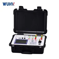


A Resonant Test System is a specialized high-voltage testing system designed to generate high AC voltages efficiently by using the resonance principle of an LC (inductor-capacitor) circuit. It is widely used for testing high-capacitance equipment such as:
High-voltage power cables
Gas Insulated Switchgear (GIS)
Large transformer windings
Rotating machines
Working Principle
The system operates based on series or parallel resonance between:
A test reactor (inductor), and
The capacitive load (i.e., the object under test, like a cable).

Result:
High circulating current flows within the LC loop.
Low power input is required to maintain high voltage.
Voltage across the test object increases significantly due to resonance.
Components of a Resonant Test System
| Component | Function |
|---|---|
| Variable Inductor (Reactor) | Tuned to match load capacitance |
| Test Object (Capacitive Load) | Cable, GIS, transformer, etc. |
| Voltage Source (Low Power) | Provides adjustable frequency and excitation |
| Excitation Transformer | Steps up low voltage from the source |
| Measuring Devices | Monitors voltage and current |
| Control and Protection Unit | Ensures safe operation, trips on overvoltage or failure |
Types of Resonant Systems
🔹 Series Resonant System (Most Common)
Inductor and test object in series.
High voltage appears across the test object.
Voltage magnification from resonance.
🔹 Parallel Resonant System
Less common; used in some specialized test circuits.
Voltage across the load is regulated by coupling capacitance.
Advantages of Resonant Test Systems
✅ Efficient Power Use: Only compensates for system losses (resonance provides natural voltage magnification).
✅ Smaller Power Source: No need for a massive generator, even at high voltages.
✅ Sinewave Output: Clean AC waveform simulates service conditions.
✅ Ideal for Long Cables or GIS: These systems have high capacitance, which suits resonance testing perfectly.
✅ Stable Operation: Voltage can be controlled precisely with frequency or inductance.
Challenges and Considerations
Tuning Sensitivity: Resonance requires precise matching of L and C.
Setup Complexity: Requires expertise and calibration.
Environmental Effects: Temperature and humidity can affect capacitance.
Flashover Risk: If resonance overshoots, the test object can be damaged.
Applications of Resonant Test Systems
| Application | Test Purpose |
|---|---|
| HV Cables (220–500 kV) | AC withstand, PD, tan δ tests |
| GIS (Gas Insulated Switchgear) | Factory and field HV testing |
| Large Transformers | Winding insulation testing |
| Motors/Generators | AC withstand test for stators |
Standards Involved
IEC 60060-3 – High-voltage test techniques for AC resonant systems
IEC 60840 / 62067 – HV and EHV cable system testing
IEEE 400.3 – Field testing of extruded cable systems using resonance
Summary
| Feature | Description |
|---|---|
| Definition | HV test system that uses resonance to efficiently generate test voltage |
| Main Use | AC withstand testing of high-capacitance equipment |
| Working Principle | Tuning inductor and test object's capacitance to resonance |
| Benefits | Power efficiency, accurate simulation, compact design |
| Risks | Overvoltage, tuning errors, insulation breakdown |