

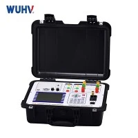


1. What is an AC Resonant Test System?
An AC Resonant Test System is a high-voltage testing system that uses series resonance between an inductor and a capacitive test object (like XLPE cable, GIS, or transformers) to generate a high test voltage with reduced power consumption. It's widely used in factory acceptance tests (FAT) and on-site commissioning tests.
2. How Does an AC Resonant Test System Work?
The system consists of a variable inductance (reactor) and a capacitive test object forming a series resonant circuit. When the frequency of the input AC power is adjusted to the circuit's resonance frequency, the voltage across the test object (capacitor) amplifies significantly due to the Q-factor of the circuit.
At Resonance:
The inductive reactance (XL) = capacitive reactance (XC)
Input current is minimized
Output voltage is maximized
The system requires much less input power than non-resonant systems
3. Why Is the AC Resonant Test System Important?
Enables high-voltage testing with compact equipment
Reduces power supply requirements
Makes long-duration withstand tests practical and safe
Ensures equipment reliability before energization
Complies with IEC/IEEE standards for factory or field testing
4. What Are the Advantages of AC Resonant Test System?
| Advantage | Explanation |
|---|---|
| Power Efficiency | Lower input power due to resonance amplification |
| Compact & Mobile | Especially with tank-type or modular designs |
| Stable Output | Less voltage distortion, suitable for sensitive tests |
| Long Test Duration | Can apply continuous high voltage for 1 hour or more |
| Reduced Stress | Prevents excessive thermal or dielectric stress on test object |
| Automatic Tuning | Intelligent systems auto-match the test object impedance |
5. What Are the Limitations of AC Resonant Test System?
| Limitation | Details |
|---|---|
| Frequency Dependent | Test voltage relies on exact tuning; detuning can cause failures |
| Initial Cost | High capital investment for large voltage/power systems |
| Complex Setup | Requires trained operators and pre-calculated capacitance |
| Not Ideal for Low Capacitance Loads | Resonance harder to achieve for small devices |
6. What Are the Components of an AC Resonant Test System?
| Component | Function |
|---|---|
| Variable Frequency Power Supply (VFPS) | Supplies low-voltage AC at adjustable frequency |
| Excitation Transformer | Steps up voltage to excite HV reactor |
| HV Reactor (Inductor) | Forms resonance circuit with test object capacitance |
| Test Object (Capacitive Load) | The equipment under test (e.g., cable, transformer) |
| Voltage Divider | Measures high voltage for feedback and safety control |
| Control System | PLC or HMI-based, controls tuning, ramp-up, data logging |
| Discharge & Grounding Unit | Safely discharges stored energy post-test |
| Partial Discharge Filters (optional) | For sensitive insulation monitoring |
7. What Are the Safety Precautions for Using AC Resonant Test System?
Always ground the system before and after testing
Use interlocked enclosures and emergency stops
Monitor for over-voltage and over-current conditions
Ensure automatic discharge circuits are working
Use remote control operation when possible
Perform capacitance pre-calculations to avoid mis-tuning
Follow IEC 61010 or equivalent electrical safety standards
8. What Are the Different Types of AC Resonant Test Systems?
| Type | Description | Use Case |
|---|---|---|
| Tank-Type (Oil-Insulated) | High-Q oil-immersed reactor in steel tank | >100 kV, high-power cable & transformer testing |
| Air-Core Modular | Portable air-core inductors, stackable | Medium-voltage, flexible field testing |
| Fixed-Frequency | Operates at standard power frequency (50/60 Hz) | Lab settings, factory testing |
| Variable Frequency | Frequency-tuned to match resonance | Field testing, wide capacitance range |
9. How Does AC Resonant Testing Compare to Other Testing Methods?
| Method | Pros | Cons |
|---|---|---|
| AC Resonant | Efficient, accurate, suitable for long cables | Complex setup, costlier |
| VLF (Very Low Frequency) | Portable, suitable for MV cables | Not suitable for HV equipment |
| DC Testing | Simple, low cost | Damaging to XLPE cables, obsolete in HV |
| Power Frequency (50/60 Hz) | Direct representation of grid stress | Requires huge power sources, impractical for long cables |
10. What Is the Future of AC Resonant Test Systems?
Digitalization: Advanced monitoring, automatic tuning, remote diagnostics
Modularization: Stackable designs for greater flexibility and mobility
Integration with AI/ML: Predictive failure analysis during testing
Eco-Friendly Designs: Use of SF6-free or dry-type insulation
Higher Voltage Capabilities: For UHV cables and future grid infrastructure (≥800 kV)
Smart Grid Readiness: Embedded data analytics and IoT connectivity