

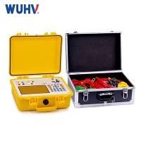


Variable Frequency AC Resonant Test Systems (Tank Type, Above 100 kV) are specialized high-voltage testing systems used primarily for on-site or factory testing of high-voltage equipment such as XLPE cables, transformers, GIS, bushings, and other substation apparatus. These systems operate by varying the frequency of the AC supply to achieve resonance between the test object's capacitance and the system's inductance, drastically reducing the required input power.
Key Features of Tank-Type VF AC Resonant Systems (>100 kV)
| Feature | Description |
|---|---|
| Rated Output Voltage | Typically from 100 kV up to 800 kV or more |
| Output Power Range | 100 kVA to several MVA |
| Variable Frequency Range | 20 Hz – 300 Hz (typical), optimized based on test object capacitance |
| System Type | Tank Type (oil-insulated reactor in steel tank) |
| Test Duration | Ranges from seconds to 1 hour depending on test standards (e.g., IEC 60840, IEC 62067) |
| Resonance Tuning | Automatically tuned by adjusting frequency to minimize input current |
| Operation Mode | Continuous or short-time (intermittent) operation |
| Control System | Fully digital PLC/HMI-based system with touch-screen interface |
| Safety | Includes interlocks, over-voltage, over-current protection, emergency stop |
Main Components
Variable Frequency Power Supply (VFPS)
Converts input power to variable frequency AC
Typically solid-state, IGBT-based inverter systems
Excitation Transformer
Steps up VFPS voltage to excite the HV reactor
Typically dry-type or oil-immersed
HV Reactor (Inductor) – Tank Type
Oil-insulated, high-Q inductance coil housed in a steel tank
Designed to work with the test object capacitance to achieve series resonance
Divider (Voltage Measurement)
Precision capacitive or resistive-capacitive divider
Measures output voltage and provides feedback
Control Unit
Manages resonance tuning, voltage ramping, data logging
Enables automatic/manual operation and fault diagnosis
HV Coupling Capacitor or Blocking Filter (optional)
For partial discharge testing or filtering harmonics
Advantages of Tank-Type Design
Compact Footprint – The oil tank allows for a high inductance in a small volume
High Stability – Excellent thermal dissipation and electrical insulation
Mobility – Skid or trailer-mounted for on-site testing
Durability – Rugged, industrial-grade build for harsh environments
Applications
| Application | Standards |
|---|---|
| HV Cable Testing (e.g., XLPE 132–500 kV) | IEC 60502-2, IEC 60840, IEC 62067 |
| GIS Testing | IEC 62271 |
| Power Transformer Tests | IEC 60076 |
| Rotating Machinery | IEEE 433 |
| Reactor and Capacitor Testing | Factory acceptance and field diagnostics |
Example Specification (Typical)
| Parameter | Value |
|---|---|
| Rated Output Voltage | 250 kV (AC) |
| Output Frequency | 30 – 300 Hz |
| Output Power | 500 kVA |
| Duty Cycle | 60 min at full load |
| Tuning Accuracy | < 0.5% of resonance frequency |
| Voltage Regulation | ±1% |
| Operation Mode | Remote & local via PLC |
Common FAQs
Q1: Why use variable frequency?
→ Allows the resonant frequency to match the LC circuit of reactor and test object, minimizing input power while reaching high test voltages.
Q2: Why tank-type reactor for above 100 kV?
→ Oil-filled tank reactors handle high inductance and voltage stress better, offering higher energy density and safety.
Q3: What's the benefit of resonance in testing?
→ Reduces power requirement, minimizes stress on equipment, and allows long-duration withstand testing.
Q4: Can this be used for PD testing?
→ Yes, with optional coupling capacitor and appropriate filtering.