

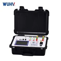


1. Technical Principle in Detail
Resonant Circuit Theory
In AC resonance testing, you exploit the resonance condition in a circuit composed of:
A variable inductance (usually a high-voltage test reactor),
The test object (which behaves like a capacitor due to its insulation characteristics),
And sometimes a tuning capacitor or a frequency-adjustable power source.
At resonance:

Where:
f = frequency (Hz)
L = inductance of the test coil (H)
C = capacitance of the test object (F)
Resonance allows for a step-up in voltage across the test object with reduced power demand from the power source. The circulating current in the LC loop is high, but the input current is low due to minimal net reactive power.
2. Types of AC Resonance Circuits
Series Resonance Circuit (most common)
Inductor and capacitive load (test object) in series.
Power source feeds the entire circuit directly.
Voltage magnification occurs across the capacitor (test object).
Parallel Resonance Circuit
Less common; used in some specialized test sets.
More sensitive to tuning and difficult to control.
3. Power Supply & Frequency Tuning
AC resonance tests are often performed with a variable-frequency power source, typically between 30 Hz and 300 Hz, because:
Lower frequencies help reduce capacitive charging current in large cables or GIS.
Tuning frequency allows you to achieve resonance without needing large inductors.
Power supplies can be:
Motor-generator sets
Frequency converters (solid-state)
HV transformers fed from an amplifier or inverter
4. What is Measured?
Key parameters:
Test voltage level (usually 1.5–2.0× rated voltage)
Leakage current
Capacitance
Dielectric loss (tan δ) (in some advanced setups)
Breakdown (if failure occurs)
This test is primarily a withstand test, not a diagnostic test. It verifies that the insulation can handle operational overvoltages for a defined duration.
Typical test durations:
15 minutes for new installations
30–60 minutes for factory tests
5. Typical Test Setup Components
| Component | Function |
|---|---|
| HV Power Source | Provides adjustable AC voltage (variable frequency) |
| HV Reactor (Inductor) | Tunes circuit into resonance |
| Capacitive Test Object | The cable, GIS, or transformer under test |
| HV Measuring Devices | Voltage divider, current transformer, etc. |
| Control & Protection Unit | Monitors, protects, and controls the test system |
6. Applications & Standards
Used For:
High-voltage XLPE power cables (e.g., 132 kV, 220 kV, 400 kV)
Gas Insulated Substations (GIS)
Transformer windings and bushings
Rotating machines (in some cases)
Standards Referenced:
IEC 60060-3 – High-voltage test techniques
IEC 60840, IEC 62067 – AC cable system testing
IEEE 400.3 – Field testing of extruded cables using AC resonance
7. Comparison with Other HV Testing Methods
| Method | Type | Advantages | Disadvantages |
|---|---|---|---|
| AC Resonance | AC, sinewave | Efficient for long cables, real conditions | Needs precise tuning and complex setup |
| DC Testing | DC | Simpler equipment, cheaper | Not suitable for XLPE (can cause damage) |
| VLF (Very Low Frequency) | Low freq AC | Portable, useful for MV systems | Not suitable for EHV or GIS testing |
| Power Frequency AC | 50/60 Hz | Ideal simulation of service condition | Requires massive power for long cables |
If you are looking for AC resonance Tester manufacturers and suppliers, please feel free to contact us for high quality and good price, we have various types of tester for sales to solve your problems.