


The working principle of a high voltage tester is based on applying a controlled high voltage to an electrical device or insulation system in order to:
Verify its dielectric strength,
Detect insulation defects, or
Ensure it can safely operate under voltage stress.
The specific operation depends on the type of high voltage tester (AC, DC, impulse, etc.), but all share the same fundamental idea:
Apply a known high voltage across insulation, monitor the resulting leakage current, and detect any breakdown or abnormal response.
1. Core Working Principle
At its core, a high voltage tester involves:
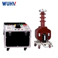
High Voltage Source: Generates AC, DC, or impulse voltage.
Test Object: The equipment under test (e.g., cable, transformer).
Measurement System: Monitors current, voltage, or discharge.
Protection Circuitry: Disconnects the system in case of failure.
Simple Concept:
Voltage Applied→Leakage Current Measured→Breakdown or Pass Detected\text{Voltage Applied} \rightarrow \text{Leakage Current Measured} \rightarrow \text{Breakdown or Pass Detected}Voltage Applied→Leakage Current Measured→Breakdown or Pass Detected
2. Working Principles by Type
A. AC High Voltage Tester (Hipot)
Applies sinusoidal AC voltage, usually at 50/60 Hz.
Simulates real operating conditions.
Measures leakage current through insulation.
If current spikes or arcs, insulation is weak or failed.
Working Steps:
Ramp up AC voltage gradually.
Hold test voltage for 1–5 minutes.
Monitor leakage current.
Shutdown if breakdown occurs.
✅ Pass: No significant current beyond leakage threshold.
❌ Fail: Insulation punctures (breakdown).
B. DC High Voltage Tester
Applies a DC voltage, usually positive or negative polarity.
Used when AC test would require too much power (e.g., long cables).
Measures steady leakage current (should decay over time).
DC is sensitive to moisture and surface tracking. It can be damaging to XLPE insulation if improperly used.
C. Impulse Tester (Lightning/Surge)
Applies high-voltage, short-duration pulse (e.g., 1.2/50 µs).
Mimics real overvoltage events (lightning, switching surges).
Output from impulse generator is applied to test object.
Measures waveform deformation or breakdown via digital recorder.
Working principle: Insulation should survive the impulse with no flashover or distortion.
D. Very Low Frequency (VLF) Tester
Applies 0.1 Hz–0.01 Hz AC to reduce reactive power demands.
Used in field testing of long MV/HV cables.
Equipment is compact and energy-efficient.
VLF systems simulate insulation stress without requiring heavy AC power.
3. Key Measurements in High Voltage Testing
| Measurement | Purpose |
|---|---|
| Leakage current | Detect insulation defects |
| Breakdown current | Confirms insulation failure |
| Insulation resistance | Quantifies insulation quality |
| Capacitance / tan δ | Measures dielectric losses |
| Partial Discharge | Locates early-stage internal defects |
4. Built-in Safety & Protection
Modern HV testers include:
Automatic shutdown on overcurrent or flashover.
Zero-start interlock (voltage must be zero before test starts).
Ground detection and safety barriers.
Discharge resistors to safely bleed residual energy after test.
5. Internal Block Diagram (Simplified)

Summary
| Component | Function |
|---|---|
| High Voltage Generator | Creates controlled HV output |
| Measurement Circuitry | Monitors voltage & current |
| Protection Circuitry | Detects failure and trips safely |
| Control System | Allows ramping, timing, pass/fail logic |